

Ceramic Technology and Processing, King
.pdfForming 183
one aluminum part. Let us walk through the mold making process to learn more about the craft.
Lower Half. Figure 6.31 is an assembly sketch of the lower pattern. Not shown is the box around the pattern that contains the plaster and makes the sides.
Figure 6.31: Mold Pattern, Lower Half. A box (A) surrounds the assembly into which the plaster is poured. The interior form consists of a base plate
(B) and a half wedge. Locking tabs (C) will register the two halves together.
184 Ceramic Technology and Processing
The box that encases the lower half is simply four slats of wood with the joints taped with masking tape and held with a rubber band. Figure 6.31 shows the lower half. These parts are marked on the figure and are as follows: lower form plate, two locking tabs, a back plate, and a half wedge. Instead of the locking tabs, one can use rubber balls. When the plaster is partially set, the balls are embedded half way into the plaster surface. The parts are assembled onto the lower form plate and held in place with rubber cement. Rubber cement does not form a strong bond, and the parts can be easily disassembled after use. Mold soap is lithium stearate paste diluted with water to a thin soap solution. It is painted onto the pattern and allowed to dry. Plaster is then poured over the pattern with a little bit just above the top. When set to a stiff mud, the excess is screed off, and the plaster is allowed to cure.
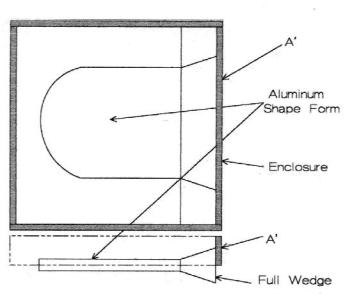
Upper Half. The upper part of the pattern consists of the shape form, the box extensions, and the full wedge. After removing the lower half pattern parts, clean the plaster by scraping off extraneous material. Do not touch the surface that will become a casting surface. The lower box is reassembled around the lower half and the upper half parts are put into place. Figure 6.32 depicts such an assembly.
A full wedge replaces the half wedge. Upper box parts are simply extensions of the box to accommodate the upper plaster. Aluminum was chosen for the form because of its dimensional stability and easy release from the plaster. After taping the joints again, coat everything with mold soap and allow it to dry. Plaster is poured over the lower half and cured. When disassembled, cleaned, and dried, the plaster mold is ready for use.
A few things should be brought to attention. Since the two halves were cast against one another they fit perfectly and the shape of the cavity is faithfully produced. The locking tabs assure that the two halves register perfectly. The wedge forms a slip reservoir, and the mold separates along the body diagonal.
Sometimes, it is necessary to make a split mold as this could be the only way to remove the part. Procedures for these molds are essentially similar to those shown here where the mold parts are cast against one another with some kind of interlocking tabs. Complex shapes can be made this way. Since it is labor intensive and the plaster has a limited life, one
Forming 185
should consider other forming methods. In the plant, the working molds are made from master case molds and the process is not so labor intensive.
Figure 6.32: Mold Pattern, Upper Half. The plaster is poured into the box (A') onto an aluminum plate that forms the casting cavity. A full wedge replaces the half wedge to form a slip reservoir.
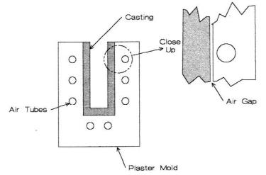
Air Release. Production molds sometimes have cloth tubes embedded in the plaster that can be filled with compressed air. A quick disconnect is cast into the plaster for introducing compressed air that breaks the cast part free. Figure 6.33 is a schematic representation.
When making the form, a wire frame is placed in the assembly and anchored to the pattern. Cloth tubes are tied to this wire frame and connected to a quick disconnect, which is exterior to the assembly. Plaster is poured over the tubes so that they are embedded in the plaster.
186 Ceramic Technology and Processing
Figure 6.33: Air Tube Release. Fabric tubes are embedded in the plaster to provide release when they are pressurized.
Check List, Plaster
•Use #1 pottery plaster.
•Store plaster in a closed container.
•Mix the plaster in one of three ways: traditional, high intensity, or hot.
•Vacuum de-air.
•Pour into forms coated with a release film and vibrate.
•Forms can be metal, plastic, sealed wood, or a composite material.
•Air release can be built into the mold if needed.
•Screen off the excess and trim the mold.
•Slowly dry from the outside surface.
Forming 187
Slip Casting
Earlier discussions on preparing slip, storing slip, and making plaster molds lead to the actual casting process itself. Slip casting is an old craft and is still extensively used for sanitary ware and technical ceramics. Often, it is the preferred manufacturing method.
Casting Mechanics
Casting proceeds by pouring the slip into the plaster mold, usually down one side to prevent incorporation of bubbles. Bottom filling is a very good technique, but lab setups are usually not this complex. Immediately upon contact, a slip cast wall is formed. This wall plays a major role in the rest of the casting mechanics. Permeability and capillary pressure of the plaster ordinarily do not dictate casting as long as they are sufficient. Since the initial cast wall is less permeable than the plaster (for fine-grained slips), it decides the casting mechanics and is the source of the rate-limiting step.
The amount of water in the plaster mold establishes the initial casting conditions. When the plaster is too dry, the cast forms entirely too fast and is irregular. When the slip is too deflocculated, the initial cast is as hard as a rock and for all practical purposes the casting stops due to the low permeability. Removing the cast will be very difficult since there is negligible drying shrinkage. Drying shrinkage is necessary to loosen the cast part. Alternatively, one can use a split mold, which works part of the time. The plaster can be tested by placing a vertical tube filled with water on top of the mold and measuring the rate at which the water is adsorbed. When the plaster is too dry, pour some water into the mold, let it sit for about five to ten seconds, pour it out, and let the mold sit for a minute or so. If the mold is too wet, put it back into the oven at 60 °C. Deflocculated slips can be adjusted in many ways. Trial and error on surfactant, pH, and binder concentrations can experimentally adjust the slip to where it casts properly. Since the addition of the binder changes the rheology, there is no simple way to predict exactly how it is going to work. One can do a simple
188 Ceramic Technology and Processing
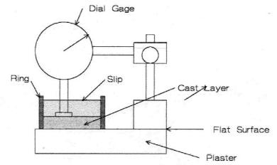
test. This test is to measure the casting rate of the slip on a plaster surface. Figure 6.34 is a sketch of such an apparatus.
Figure 6.34: Casting Rate Device. A dial micrometer is used to measure the thickness of the cast layer with time.
The plaster can be cast on a pane of glass. Glass imparts a smooth and flat surface to the plaster needed as a base for the dial micrometer. The mold is just a short section that is cut from a plastic pipe and is sanded smooth. Keep the slip covered between measurements to keep it from drying. Measurements are timed, of course, and taken in a different place each time. Lift the micrometer and clean the tip after each measurement. Thickness versus time will plot as a parabola if it behaves as it should.
Coarse-grained slips with high-solids loading can cast faster depending on the PSD in the fines. The test shown in Figure 6.34 may need to be scaled up because of the large grain size.
After the measurements are completed, examine the cast part while it is still wet. Casts can be flabby, hard, or somewhere therein. The best
Forming 189
consistency is somewhere therein but leaning toward the hard side. Dry the disc and fire it. Measure the drying and firing shrinkage and density. A linear shrinkage of a little less than 20% is achievable for fine-grained ceramics. Structural ceramics often have 100% of fired theoretical density as a goal. Coarse grained ceramics can have almost no shrinkage, and the density is usually between 65-90%, depending on the formulation. Lots of materials fall between these end members. Data from reverse engineering will help to guide the choice of formulation.
Mold Filling
It was common practice to place a ring on top of the mold to act as a slip reservoir. As casting proceeds, the slip is drawn down into the mold keeping the mold full of slip. To prevent drying, the reservoir is covered during casting. A watch glass or plastic film is useful for this.
In ordinary slip casting, there are two methods: drain casting and solid casting. In drain casting, the cast wall is built up to the desired thickness and then the remaining slip is poured out. One can measure the wall thickness with a probe. This method is not too accurate but is often good enough for a lab procedure. If more accuracy is needed, one can use appropriate micrometers for this type of measurement. Solid casting is a procedure where the slip is cast into a solid part, just like the name implies. One can locate the top of the cast with a probe. It is cast a little long and later trimmed off. To avoid distorting the part when trimming, always cut toward the plaster. Solid casting can also be used to make a hollow part such as a tube in which case a central core is placed in the mold. The core can be a casting surface such as plaster, in which case it should be collapsible or it will never be removable from the mold. Since the casting will shrink upon drying, it will crack if the core is left in. This makes timing an important consideration. Pull the core just when the cast is completed. One can also use rigid plastic foam cores. These are more flexible and put less stress on the casting. Polystyrene foam is very soluble in acetone and will collapse when squirted.
190 Ceramic Technology and Processing
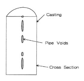
Pipe. Pipes are voids in the center of the casting that result from pockets of slip that are cut off from the slip supply. Entrapped slip will continue to shrink as it loses water, creating voids. Figure 6.35 shows such pipe voids.
Figure 6.35: Pipe. The figure is shown cut in half. Pipes are the central voids.
Sometimes, pipes are not a problem as they do not extend to the surface. When it is a problem, there are a couple of ways to cope with it.
While the article is casting, the mold can be vibrated. An electrical, vibrating table is useful, with a fixture holding the mold on the table. Vibration intensity varies with a rheostat set at an intermediate value that causes enough vibration intensity to keep the slip fluid. Fine-grained slips are pseudo-plastic, so vibration makes sense. Coarse-grained slips have serious settling problems and vibration is not such a good idea. With the coarse grains nestled at the bottom and the fine grains on the top, the body will not shrink uniformly during firing, and will most likely crack. Settling can be slowed by increasing the slip viscosity. Coarse grains are not
Forming 191
sensitive to surface chemistry as gravity dominates settling. An increase in viscosity will slow things. One can accomplish this by increasing the fines, flocculating the fines, or by adding an organic thickener. However, higher viscosities will also slow the casting rate that in turn increases settling time.
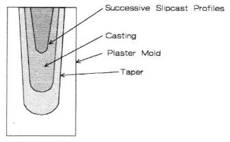
The second remedy is to use a tapered mold, illustrated in Figure
6.36.
Figure 6.36: Tapered Mold. The taper avoids pipes as the central portion of the cast is always connected to the slip reservoir.
As the body casts, the taper prevents entrapment of air and a voidfree solid cast results. Vibration is useful as the part casts; this helps to keep the slip fluid. When the cross section is square, fluid dynamics can draw air from the mold into the cast at the corners. Beveling the corners on the pattern helps to avoid this problem. Corner air bubbles are more likely when the plaster is too dry and the casting rate is high, in which case prewet the plaster with water to slow the casting rate. This tapered mold shape is probably not the geometry that is desired. Green machining, which will be described in Chapter VII, is a good way to reshape the part. In the lab, the priority is often to make a few parts for testing. The problem of producing the part will be addressed later. Production is inescapable if the research is successful. Different forming methods should not be overlooked should you get yourself into trouble making solid cast parts.
192 Ceramic Technology and Processing
Long parts. When casting long parts, the slip at the bottom of the mold cavity is at a significantly higher pressure than the slip at the top. Hydrostatic pressure causes the bottom to cast at a higher rate than the top, producing a tapered wall. When solid casting, this is an asset to reduce pipe just as a tapered mold does. When drain casting (say a tube), a tapered wall may not be acceptable. The mold can be laid almost flat with vertical tubes at each end for the fill and for the riser. The riser end has to be higher than the fill end for air bubbles to escape. Coarse-grained slips will settle toward the bottom side of the cavity that it creates in homogeneity.
Drying Slip Cast Parts
It is usual to just air dry the part in the mold to the point where it is self supporting and can be removed. Keep in mind that water vapor is denser than air. One should tilt a drain cast tube in the mold at an angle to allow the water vapor to flow out. Turn the mold periodically for uniform drying. Large parts are more sensitive to drying stresses than small parts. Humidity drying is a very useful process especially for larger pieces, but this is not a lab process. Restricting the drying rate is an alternative. Since there should be some drying shrinkage, let the part equilibrate slowly in its moisture content to minimize stresses. Drying can also be done in an oven at 40-60 °C. It was mentioned earlier that solid cast parts are time sensitive. Experience will establish the right time to remove the part. Leaving it in too long can result in a reject. Always, set the part on a permeable or perforated base so that it dries uniformly. Microwave or dielectric drying has been around for a long time, but is not widely used. Depending upon absorption of the microwave energy in the part, heating can be superficial, creating temperature gradients or penetrating. Suppliers of this equipment can run tests.
Part Release
It is frustrating when the part will not release from the mold. There are several things that can be done to alleviate this situation.
- Drying shrinkage is necessary for the part to release from