

Ceramic Technology and Processing, King
.pdfGreen Machining 223
an abrasive point in place of the rotating centers. With the ceramic mounted, the other hand rotates the part. Figure 7.6 depicts another idea for grinding cylinders.
Figure 7.5: Lapping Fixture, Cylinder. The green part is turned by hand on a SiC-coated, abrasive lap.
Figure 7.6: Lapping Fixture Alternate, Cylinder. Another design for green machining cylinders has more size flexibility.
224 Ceramic Technology and Processing
This fixture is different because the thickness of the hardened steel facing sets the diameter of the cylinder. The facings are held in place with flat head machine screws. Again, hold the part with hand pressure by pushing on the right center, and rotate the part with the other hand as before.
3.0 TOOLING
Tooling falls into two classes: improvised tooling with fixtures and conventional machine tooling. Grinding is going to be emphasized.
Abrasives
Most common abrasives are bonded diamond and Silicon Carbide abrasives. One can use Silicon Carbide as a grain or as a bonded abrasive article, usually as a coated abrasive. When green machining, one uses an intermediate grit size. Since fine-grit, bonded abrasives tend to blind, they are ineffective. Coarse grit is too rough and can damage the part. The grit size range of 60 to about 120 is generally useful, but one can use a little finer grit size.
Coolants
One generally uses a coolant to wash away the swarf and keep the part from overheating. The coolant also washes the swarf out of the abrasive face, keeping it free to cut. Depending upon the binder, one can use water or Kerosene. Often, the binder will be water soluble, so this will exclude water as the lubricant. However, there is an alternative. The part can be bisque fired, and which water is the coolant of choice for grinding. The extra firing is not a major issue in a lab procedure, but it might not be cost effective in production.
Green Machining 225
The type of equipment will determine how the coolant is applied. If it is a lap or drip, one can use a squirt bottle. If it is on a machine tool, there will probably have to be a bucket and a circulating pump. Not all machine tools handle coolants, so one will need to improvise or try other equipment.
Kerosene is flammable, so it will require precautionary measures. Motors should be explosion-proof or better still, remote. The same is true with switches. If there is a fair amount of work, one will need to rig a vent. It is not a good idea to ingest this mist, nor to have its concentration built up to explosive concentrations. A small amount of Kerosene is not too bad on your hands. A large amount of Kerosene will dry and chap one's skin, so wear rubber or vinyl gloves. Never work without eye protection. Fire is the principal hazard.
Machine Tools
Machining operations generally are designed to make shaped surfaces such as planes, right circular cylinders, spheres, and cones. It is unlikely that special contouring equipment will be available.
Cutoff
One uses diamond cutoff saws for cutoffs. Diamond blades have the following characteristics: they have a continuous rim, are thin, and are metal bonded; probably with a high diamond concentration. For 3-6" diameter blades, the thickness should be no greater than about 0.030". Thicker blades put excessive stress on the part. Again, the grit size should be intermediate and not too fine.
A cutoff is done with a coolant to remove the swarf. Otherwise, the cut will gum up. For small work, a lapidary saw that dips the blade into the Kerosene coolant is not very precise, but can cut off the end of the part. Figure 7.7 is of a small cutoff saw that is suitable for small green machining cutoff work.

226 Ceramic Technology and Processing
Figure 7.7: A cutoff machine. Diamond wheels are used to cut off the ends of parts or for cutting slots. (Courtesy of Buehler, Ltd.)
Larger equipment should be set up with a coolant supply and safety features. If equipped with a coolant capability, use a surface grinder with a cutoff blade. The same safety precautions, as above, will apply. Hold the part with a fixture on the bed. If it is flat, it can be blocked in with steel on the magnetic chuck. If it is round, one can use a V-shaped block. Near the end of the pass, the cut will break out, leaving a chip. Cut only part way through and then cut in from the other side to put the breakout in the center where it will be smaller and less obvious. One can also back up the part with a similar expendable piece to reduce any chip-out.
Surface grinders are an exception. Most cutoff on a green body is done off hand and the part trued up later. Wire saws are also available and have the advantage of not jamming the blade.
Green Machining 227
Laps
A lap with a Silicon Carbide paper is very useful for green machining. One can also use it with loose, abrasive grain. Apply Kerosene with a drip or squirt bottle. Hold the paper in place with a retaining ring or a pressure sensitive adhesive backing. When a loose paper starts to slip, wet the back side and it will stay in place. Most of these laps are 8 inches in diameter and have the choice of two speeds. They have a splash bowl and a drain that makes it easy to set up for the coolant. While designed for metallography, they are also useful for green machining of small parts. Grit size of the coated, abrasive paper is most useful in the coarser grits, from 60 to 120 grit.
Core Drills
These are abrasive tools used for drilling holes. A coolant is always used to carry off the swarf; introduce it down through the center of the drill. It is common to have these mounted on a drill press where there is a rig to take away the coolant. The working part is a metal-bonded, diamondcontinuousrim tool. Again, the grit size is moderately coarse. Let the drill do the work and do not push it too hard. There will be a breakout when the drill completes the cut. One can back up the piece by placing a blank scrap underneath for support to limit breakout, or drill in from both sides toward the center.
Form Grinding Tools
Grinding wheels can be configured to grind a contour. This is essentially a router using an abrasive cutter. A router is a versatile forming tool much used in wood working. One can use it as a joiner cutoff for making contoured edges, rabbets, dados, or to drill holes.
One creates the form during manufacture and trues it with a
228 Ceramic Technology and Processing
diamond or crush-type, trueing device. As the grinding wheel rotates, the trueing device shapes the surface of the wheel to the desired contour. In use, the rotating part is fed into the rotating form grinder to make the desired shape. One configures spark plugs this way. In the lab, there usually are not enough parts needed to go through all this trouble. If a machine shop that has a tracing attachment and a tool post grinder attachment on its lathe can be located, then that might be a suitable way to go. Another alternative is to locate a pattern shop that has contouring capability, grinding and cutting tools.
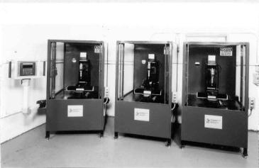
Green machining equipment has been developed for larger scale operations as well. Figure 7.8 depicts a green machining center that uses three machines.
Figure 7.8: Green Machining Center. Commercial green machining centers that feature abrasive cutting tools are available. (Courtesy of Chand Kare)
These are grinding machines that are CNC controlled, and each has nine axes for setups. With this much flexibility, coupled with lateral motion of the work piece, many shapes can be machined. This is somewhat elaborate for a standard ceramic lab; it all depends on the research
Green Machining 229
requirements. Metal bonded mounted points of different contours are chucked in precision high speed spindles. Grinding is done under dry conditions in the sealed enclosure, and there is a facility for connection to a dust collector. The stresses and temperature of the work piece are affected by the speed control of the mounted point, depth of the cut, and the grit size of the grinding tool. This is more critical when grinding dry than when grinding wet.
Check List, Green Machining
•Grinding is the preferred method for green machining.
•Fixturing is a quick and accurate way to shape the part.
•Wear plates control the depth of cut.
•Coolants are needed to wash away the swarf.
•Kerosene is a preferred coolant for water soluble binders.
•Water is the preferred coolant for bisque-fired parts.
•Machine tools are available for green machining.

8
Firing
1.0 INTRODUCTION
Ceramics are sintered by raising them to a high temperature. This process consolidates the material, increases its strength, and usually causes it to shrink. This chapter includes sections on equipment, setting practices, firing procedures, hot pressing, and hipping.
2.0 EQUIPMENT
A variety of furnace designs are commercially available for all kinds of applications. It is better to purchase equipment than to build it yourself. In either case, there are design features that one should follow or look for.
Not all purchased furnaces are free from design or manufacturing errors. It is advisable to carefully check out the equipment before acquiring it. Rather than trying to be encyclopedic, the purpose of this section is to illuminate furnace design errors in the belief that one can avoid such errors in the future. Names of manufactures will not be included, as there have been many changes in furnace design and materials in the past few years.
230
Firing 231
Box Kilns
One can open these boxes from the front, the bottom, or the top.
Configuration of box kilns
Front. A problem with these kilns is that the configuration of the door is unstable with use. The steel supporting structure warps with use because of overheating and the door ceases to fit. This problem is progressively degenerative. The front of the setting will be at a lower temperature than the back. Backup insulting brick will also overheat, causing them to shrink. Bricks fall out. Another way to make a door is to pile bricks in the opening to seal it off. When the joints are staggered properly, the door will be okay, but it will not last. There are always odd shapes to fill the openings that are lost or worn out. And this can work, as it has for millennia.
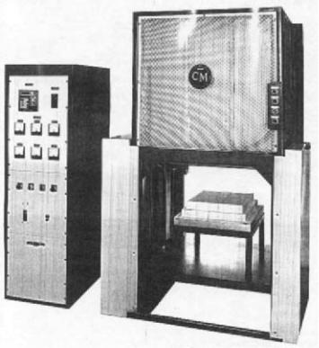
Drop Hearth Kilns. Since access to the hearth is unobstructed, drop hearth kilns are very handy to load. However, if the setting is precarious, the piece may topple out when one opens the kiln after firing. Hearths can shake as they are moved up and down. Figure 8.1 depicts a lab size, electrically heated, drop hearth kiln.
There are several features about this design that are important. The size of the furnace is large enough to keep the ware away from the proximity of the heating elements. A 1-inch to 2-inch clearance is best. This ample furnace has a hearth about 16 inches by 16 inches. A large box also helps in air circulation, especially for an open setting. A ball-screw drive lifts the hearth. Mechanical lifts, such as a smooth ball screw, provide positive movement that results in little shaking. Refractories on the hearth are staggered so that there is no through line of sight for radiation. This is standard construction wherever there is an opening to the interior of the box. Raised hearths or fiber insulated hearths are necessary, as cold hearths produce uneven firing. In the kiln shown, the hearth plate has a shoulder on both the back and front. It is common practice to set pieces on a bed of
232 Ceramic Technology and Processing
refractory grain, and one can use these shoulders as guides for screeding the grain bed flat. If needed, one can add a raised hearth set on blocks or vertical refractory tubes counter bored into the existing hearth stuffed with refractory fiber. Heating is with MoSi2 elements that can be set to 1700 °C or higher. Higher temperatures are hard on both the elements and fiber refractories, but it can be done. Another appreciated feature is the expanded metal cover that is offset from the kiln shell. This is cool and prevents burns when the operator lurches against the furnace. Controls and gages are straightforward and can be programmed to just about any cycle, subject to the cooling rate maximum of the kiln.
Figure 8.1: Laboratory Furnace, Electric. Drop hearth kilns allow access to all sides of the setting. (Courtesy of CM Furnaces).