

47.5.3 Speech coding and channel coding
The speech coder is a regular pulse excited linear predictive coder (RPE-LPC) with long term prediction. This provides a net bit rate of 13kbit/s. It is a block based coder where the input samples are analysed in blocks with a 20ms duration. Work is also being carried out to specify a half rate speech coder which will effectively double the system capacity of GSM.
Before being assembled into the timeslots and frames, the digital speech and signalling data is encoded and interleaved. The speech coder output is divided up into three classes of bits and the most sensitive bits are encoded by adding parity check bits followed by a convolutional coder. Signalling data is encoded using a FIRE code. A process of interleaving is then used to spread the data blocks over a number of bursts.
For speech, an interleaving degree of 8 is used, i.e the speech block is spread over 8 bursts, whilst an interleaving degree of 4 is used for signalling. This overall process is shown in Figure 47.11, and the combined use of coding and interleaving provides good protection of channel data from the fading, dispersion and interference effects on the radio path. With the addition of frequency hopping and diversity techniques, the GSM air interface is particularly robust.
One of the penalties to be paid for this is the overall transmission delay. The speech coder contributes about 25ms and the channel coding and interleaving a further 37ms. The rest of the transmission delay budget allows for analogue to digital conversions, 16kbit/s transmission and switching in various parts of the network. The overall one way transmission delay thus amounts to around 90ms. Such a delay means that echo control is necessary even on short national calls.
Table 47.4 GSM logical channels
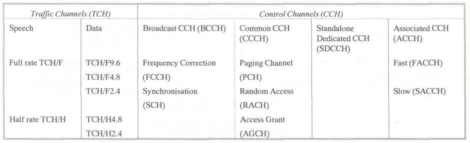
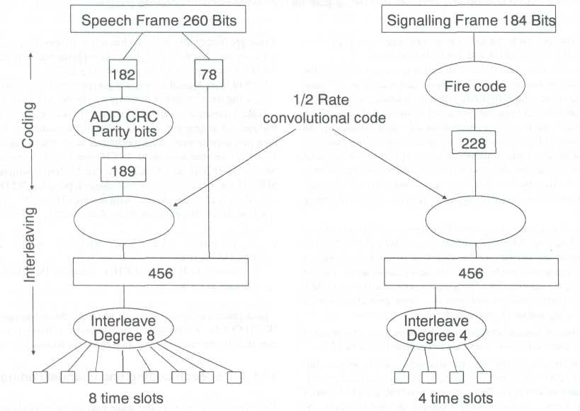
Figure 47.11 GSM channel coding and interleaving
47.5.4 Gsm signalling
Figure 47.12 shows the overall signalling model. The Air Interface uses LAPDm Layer 2 signalling protocol and this is also used for the A-bis, BTS to BSC interface.
The layer 3 protocol consists of three sublayers, dealing with radio resource management (RR), mobility management (MM), and connection management (CM). Radio resource management is concerned with managing the logical channels, including paging, channel assignments, handover, measurement reporting, and other functions.
The mobility management layer contains functions necessary to support the mobility of the user which include authentication, location updating, attach and detach of IMSI (International Mobile Subscriber Identity), and registration. The connection management layer is concerned with call control, establishing and clearing circuits, management of supplementary services and the short message service.
The BSC to MSC A-interface, and the various MSC to Register interfaces employ CCITT No.7 signalling using the Message Transfer Part (MTP), Signalling Connection Control Part (SCCP), Transaction Capabilities Part (TCAP) and Mobile Application Part (MAP).
An example of the signalling messaging for establishing a mobile originated call is shown in Figure 47.13. The key events are:
Request and assignment of a channel, between MS and BSS.
A service request procedure which accesses the VLR.
An authentication and ciphering exchange which validates the mobile user and sets the encryption cipher.
Call set up which includes sending of dialled digits and establishing the connection.
Location updating is shown in Figure 47.14 An update request is indicated by the mobile and passed to the VLR in the new location area. The new VLR requests the IMSI from the old VLR and then signals the new location to the HLR. The HLR provides the subscriber data to the new VLR and cancels the subscriber entry in the old VLR. Finally a confirmation message is set back to the mobile. There are, of course, many other signalling exchanges, dealing with mobile terminating calls, supplementary services, and short message service. There is not space in this chapter to deal with the detailed signalling for these cases; the examples above describe the general principle and illustrate the roles of the MS, BSS, MSC, VLR and HLR.
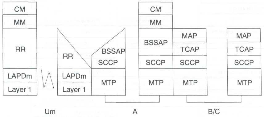
Figure 47.12 GSM signalling model