

47.2.6 Power control
Since the size of a cell may be anything from one kilometre to tens of kilometres across, it is not necessary for a mobile to transmit on full power at all times in order to maintain a satisfactory signal level at the base station's receiver. Most cellular standards therefore incorporate mobile power control, the base station commanding the mobile to transmit at one of a number of power levels. As the mobile moves closer to or further from the base station, further commands are issued to keep the received signal level to prescribed limits. By reducing the average mobile power level, co-channel interference is reduced, improving overall system quality.
47.3 Radio planning
As previously described, cellular radio re-uses the same radio channels in different cells and because of this re-use, two mobiles using the same channel in different cells may interfere with each other, a phenomenon known as co-channel interference. The key objective of planning a cellular radio system is to design the cell repeat pattern and frequency allocation in order to maximise the capacity of the system whilst controlling co-channel interference to within acceptable limits.
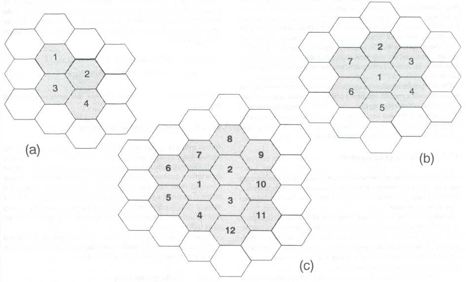
Figure 47.4 Cell repeat patterns: (a) four cell repeat; (b) seven cell repeat; (c) twelve cell repeat
47.3.1 Cell repeat patterns
The cell plan has to be chosen such that the number of channel sets (N) fit together in a regular fashion without gaps or overlaps. Only certain values of N achieve this, and typical arrangements of interest to cellular radio are N = 4, 7 and 12 as shown in Figure 47.4. The value of N has a major effect on the capacity of the cellular system.
As the number of channels sets is decreased, the number of channels per cell increases, hence the system capacity increases. For example, if there are a total of 140 channels available, a 4 cell repeat pattern would provide 35 channels per cell, whilst a 7 cell would provide 20 channels per cell.
On this basis, the smallest possible value of N seems desirable. However, as N decreases, so the distance between cells using the same channels reduces, which in turn increases the level of co-channel interference.
The repeat distance D and the cell radius R are both related by the geometry of the cell pattern. These are shown in Figure 47.5 and Equation 47.1.
![]()
In practice, in a real network, it is not possible to achieve a regular cell pattern. This is because radio propagation at the frequencies used by cellular radio systems is affected by the terrain and by buildings, trees and other features of the landscape.
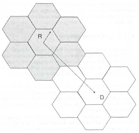
Figure 47.5 Frequency re-use - D/R ratio
47.3.2 Co-channel interference
Generally, a mobile will receive a wanted carrier signal (C) from the base station serving the cell in which it is located, and in addition, interfering signals (1) from other cells. The carrier to interference ratio C/I is related to the re-use ratio D/R. Cellular radio systems are designed to tolerate a certain amount of interference, but beyond this, speech quality will be severely degraded. The TACS cellular system, for example, will work with a C/I down to around 17dB. This lower limit on C/I effectively sets the minimum D/R ratio that can be used.
The two key factors in ensuring that good quality transmission can occur between a mobile and base station are that the wanted signal strength is sufficiently large, that is, above the receiver threshold sensitivity, and that the interference level is low enough to give an adequate C/I ratio. Both of these factors depend on the radio propagation between the mobile and base stations.