

47.3.3 Radio propagation
There are a number of elements which contribute to the received signal strength at a mobile. Firstly, for a line of sight path, there is a free space path loss which is related to the radial distance between base station and mobile.
In addition to this loss, where there is no direct line of sight path, there will be a diffraction loss resulting from obstructions in the path. In general there will also be an effect due to multiple signals arriving at the mobile due to reflections from buildings and other terrain features. This multi-path effect will result in signals either adding constructively or destructively.
As a mobile moves around within a cell it will experience varying signal, as shown in Figure 47.6, due to these factors. Fast fading is caused by the multipath effect, and occurs with only a small movement of the mobile. This is also known as Rayleigh fading. Slow fading is mainly caused by terrain features and occurs over large distances of hundreds of metres.
In addition, the path loss is also dependent upon the type of terrain, for example, urban with dense buildings, or rural with trees, or even over water. The height of the mobile and base station above ground level also affects the propagation, although the mobile height is not usually a variable.
Predicting path loss is an essential part of radio planning, and because of the large number of contributing factors, empirically based formulae are used. The most widely used formula is the Hata model (Hata, 1980) which is based on the propagation measurement results of Okumura et al. (1968).
Hata's basic formula for the total path loss, Lp, is given by Equation 47.2 where f is the carrier frequency in MHz, k is the base station antenna height, h is the mobile antenna height, R is the radial distance in kilometres, and a(h ) is the mobile antenna height correction factor.
Lp (dB) = 69.55 + 26.16log(fc) – 13.82log(hb) – a(hm) + (44.9 – 6.55log(hb))logR (47.2)
Correction factors can be used to take into account the type of terrain
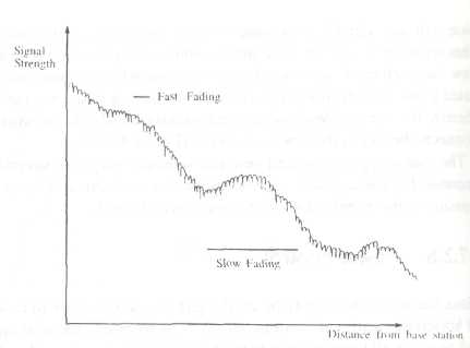
Figure 47.6 Fading effects
47.3.4 Practical radio planning
Armed with a propagation model it is possible to calculate both the wanted signal strength and the interference level for all locations in a cell. Generally this is done using a computer based tool which can draw upon a database of cell site information and terrain data. Some advanced tools can also take account of diffraction losses. For practical purposes a planner will aim to achieve the required signal strength and C/I ratio over 90% of the cell coverage area, by varying antenna heights, transmitter powers, frequency allocations and other factors as appropriate.
To simplify calculations, an allowance for Rayleigh fading and shadow fading is usually made within the system power budget. A typical power budget is shown in Table 47.1.
47.3.5 Adding capacity
Once a cellular network has been planned to provide overall coverage, there are a' number of ways of adding additional capacity. A simple and cost effective option is to allocate further radio channels to existing cells. However, this can only be done by an extension band, for example the ETACS allocation in the UK. Other alternatives involve rearranging the cellular plan, either by cell splitting or by sectorisation.
Cell splitting is achieved by dividing an existing cell up into a number of smaller cells, by adding additional base stations as shown in Figure 47.7; it is then necessary to reallocate the radio channels. By repeatedly splitting cells; the cell size, and hence the system capacity, can be tailored to meet the traffic capacity requirements demanded by customer behaviour in all areas.
Table 47.1 Typical power budget (TACS) (1 = Key planning parameters)
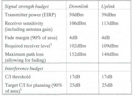
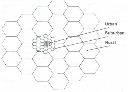
Figure 47.7 Cell splitting
In rural areas, cells may be 20km to 30km in radius. In practice, as cell sizes decrease, propagation effects, particularly in city areas, cause an increase in co-channel interference, even if the repeat pattern is maintained. Also, as cell sizes decrease, it becomes increasingly difficult to find suitable base station sites, which need to be accurately positioned in order to keep to a regular pattern.
The cost of providing and maintaining a large number of individual base stations is also a factor, such that in addition to cell splitting, sectorisation of cells is commonly used in urban areas.
In a regular cellular layout, co-channel interference will be received from six surrounding cells which all use the same channel set. One way of cutting significantly the level of interference is to use several directional antennas at the base stations, with each antenna illuminating a sector of the cell, and with a separate channel set allocated to each sector.
There are two commonly used methods of sectorisation, using three 120 degree sectors or six 60 degree sectors as shown in Figure 47.8, both of which reduce the number of prime interference sources to one. This is because, of the six surrounding co-channel cells, only one will be directed at the wanted cell.
A disadvantage of sectorisation is that the channel sets are divided between the sectors such that there are fewer channels per sector, and thus a reduction in trunking efficiency. This means that the total traffic which can be carried for a given level of blocking is reduced. However, this effect is offset by the ability to use smaller cells, such that the end result is a significant increase in total capacity.

Figure 47.8 Sectorisation
Exercise 1 Learn the words and word combinations
a cellular network |
сеть радиосвязи с сотовой структурой |
paging call |
поисковой вызов, передача сигналов поискового вызова |
predesignated threshold |
предварительный обозначенный порог |
frequency allocation |
распределение частот (между службами) |
ETACS (Extended Total Access Communication System) |
расширенная система связи с полным доступом |
overhead information |
служебная информация |
Cellular radio systems |
сотовые системы связи |
to be in decline |
быть в состоянии упадка, идти на убыль |
frequency band |
диапазон частот; полоса частот |
assigned (-frequency) band |
полоса частот, выделенная для радиостанций |
attenuation band |
полоса ослабления, полоса затухания |
broad band |
широкий диапазон частот |
broadcast band |
радиовещательный диапазон частот (535 Гц – 160 кГц) |
citizen band |
диапазон частот, выделенный для частной и служебной связи (26, 965-27, 405МГц; 460-4709-МГц) |
communication band |
диапазон (полоса) частот радиосвязи |
exclusive band |
диапазон частот, запрещенный для использования |
channel spacing |
разнесение каналов; канальный интервал |
GSM (Global System for Mobile Communications) |
глобальные системы мобильной связи |
overlapping channel spacing |
расстановка каналов с перекрытием по спектру |
incompatible |
несовместимый, невзаимозаменяемый |
cell |
сота, элемент, ячейка |
radio transparent coverage |
радиопрозрачное покрытие |
frequency coverage |
перекрываемый диапазон частот, перекрытие по частоте |
a mobile services switching centre (MSC) |
мобильный центр коммутации |
a digital telephone exchange |
цифровая телефонная станция |
software |
программное обеспечение |
link |
связь, соединение; линия связи |
backbone link |
магистральная линия связи; магистральный канал связи |
bandwidth-limited link |
линия связи с ограниченной полосой пропускания |
bidirectional link |
двусторонняя линия связи |
communication(s) link |
линия связи |
data link |
линия (передачи) данных; канал (передачи) данных |
dedicated link |
закрепленный (выделенный) канал связи |
the public switched telephone network (PSTN) |
телефонная сеть общего пользования |
outgoing calls |
исходящие звонки |
incoming calls |
входящие звонки |
fixed telephones |
стационарные телефоны |
to be dependent upon |
зависеть от |
channel sets |
группа (набор) каналов |
signalling channel |
канал сигнализации (тональной), канал передачи служебных сигналов |
signalling |
передача сигналов; телеграфирование, вызов (в телефонии) |
an area identifier |
определитель; устройство распознавания; устройство опознавания |
an area code |
код зоны |
coverage area |
зона обслуживания |
self-checking code |
код с самопроверкой |
single error-correcting code |
код исправления одиночных ошибок |
standard code |
правила эксплуатации |
specific code |
абсолютный код |
termination code |
код завершения |
in the land to mobile direction |
в направлении от станции к телефону |
in the mobile to land direction |
в направлении от телефона к станции |
location updating |
обновление (изменение), определение место нахождения |
to re-use |
использовать многократно |
terrain diffraction |
дифракция на рельефе местности |
Exercise 2 Read the text
Exercise 3 Find the Russian equivalents for the following English words and word combinations
|
|
|
|
|
|
|
|
|
|
|
|
|
|
|
|
|
|
|
|
|
|
Exercise 4 Answer the following questions:
1 |
When and where were the basic principles of cellular systems established? |
2 |
Why are different and incompatible cellular standards in use throughout the world? |
3 |
What are the main principles of network configuration, signalling and location registration? |
4 |
Is it difficult for you to describe in English the signalling procedures for mobile to land and land to mobile call set up? |
5 |
Why do most cellular standards incorporate mobile power control? |
6 |
What is the key objective of planning a cellular radio system? |
7 |
Is it possible to achieve a regular cell pattern in practice (in a real network)? |
8 |
What are the two key factors in ensuring that good quality transmission can occur between a mobile and base station? |
9 |
What affects the propagation? |
10 |
What are the main ways of adding additional capacity to a cellular network? |
11 |
Do cell splitting and sectorisation have any advantages and disadvantages? What are they? |
Part II (47.4 – 47.4.5)