

III. Look through Text 6 to find out the following:
How is a process made by a sequentially controlled system defined?
What is the difference between a time-driven sequence and an event-driven one?
What is the classic example of a sequentially controlled system?
Give some more examples of sequentially controlled systems.
IV. Answer the questions of Ex. III.
V. Read text 6 attentively. Translate it orally. Sequentially Controlled Systems
A sequentially controlled system controls a process that is defined as a series of tasks to be performed—that is, a sequence of operations, one after the other. Each operation in the sequence is performed either for a certain amount of time, in which case it is time-driven, or until the task is finished (as indicated by, say, a limit switch), in which case it is event-driven. A time-driven sequence is open-loop because there is no feedback, whereas an event-driven task is closed-loop because a feedback signal is required to specify when the task is finished. The classic example of a sequentially controlled system is the automatic washing machine. The first event in the wash cycle is to fill the tub. This is an event-driven task because the water is admitted until it gets to the proper level as indicated by a float and limit switch (closed loop). The next two tasks, wash and spin-drain, are each done for a specified period "of time and are time-driven events (open loop). A timing diagram for a washing machine is shown in Figure 1.10. Another example of a sequentially controlled system is a traffic signal. The basic sequence may be time-driven: 45 seconds for green, 3 seconds for yellow, and 45 seconds for red. The presence or absence of traffic, as indicated by sensors in the roadbed, however, may alter the basic sequence, which is an event-driven control. Many automated industrial processes could be classified as sequentially controlled systems. An example is a process where parts are loaded into trays, inserted into a furnace for 10 minutes, then removed and cooled for 10 minutes, and loaded into boxes in groups of six. In the past, most sequentially controlled systems used switches, relays, and electromechanical timers to implement the control logic. These tasks are now performed

more and more by small computers known as programmable logic controllers (PLCs), which are less expensive, more reliable, and easily reprogrammed to meet changing needs—for example, to put eight items in a box instead of six.
T E X T 7.
S E R V O M E C H A N I S M S
Read and give a short summary of Text 7.
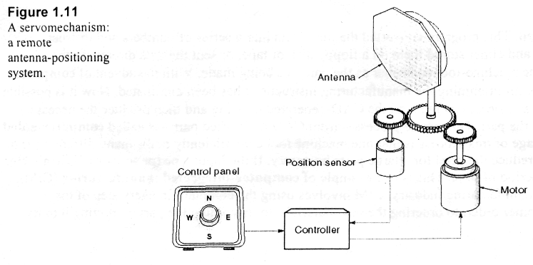
Servomechanism is the traditional term applied to describe a closed-loop electromechanical control system that directs the precise movement of a physical object such as a radar antenna or robot arm. Typically, either the output position or the output velocity (or both) is controlled. An example of a servomechanism is the positioning system for a radar antenna, as shown in Figure 1.11. In this case, the controlled variable is the antenna position. The antenna is rotated with an electric motor connected to the controller located some distance away. The user selects a direction, and the controller directs the antenna to rotate to a specific position.
Make a list of terms from Text 7 and memorize them.
Translate Text 7 in writing.
T E X T 8.
N U M E R I C A L C O N T R O L
I. Give the Russian equivalents to the following international words and word-combinations:
Electromechanical control system, to direct, physical object, radar antenna, electric motor, operator, parameter, controller, details, computer program, instructions, efficiently.
II. Memorize the meaning of the following words and word-combinations from Text 8.
1. automatic assembling machine -автоматизированное сборочное устройство
2. numerical control machine -устройство с числовым программным управлением (станок)
3. output velocity -скорость на выходе
4. lathe -токарный станок
5. milling machine -фрезерный станок
6. cutting-tool speed -скорость резца
7. cutting depth -глубина резания
8. feed rate -скорость подачи
9. computer-aided design -автоматизированное проектирование
10. computer-aided manufacturing -автоматизированное производство
11. computer-integrated manufacturing -комплексно-автоматизированное производство
Ш. Look through Text 8 to find out the following:
Where is numerical control used?
What is the function of the controller?
How long have numerical control machines been used?
What program is used to read the CAD-generated drawing?
How is this whole process called?
What is the advantage of this process?
What does computer-integrated manufacturing involve?
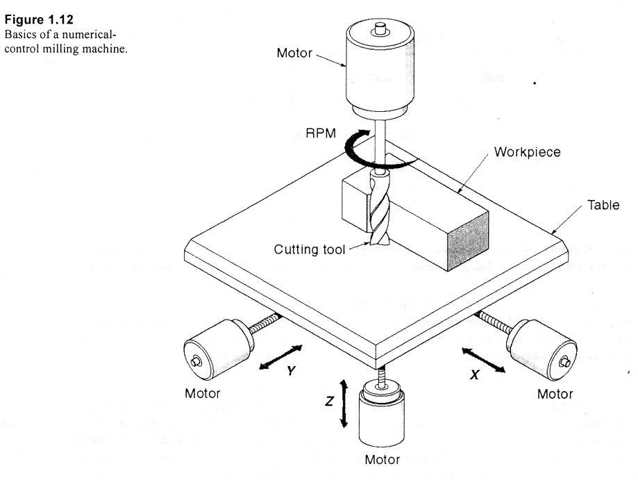
Numerical control (NC) is the type of digital control used on machine tools such as lathes and milling machines. These machines can automatically cut and shape the workpiece without a human operator. Each machine has its own set of axes or parameters that must be controlled; as an example, consider the milling machine shown in Figure 1.12. The workpiece that is being formed is fastened to a movable table. The table can be moved (with electric motors) in three directions: X, Y, and Z. The cutting-tool speed is automatically controlled as well. To make a part, the table moves the workpiece past the cutting tool at a specified velocity and cutting depth. In this example, four parameters (X, Y, Z, and rpm) are continuously and independently controlled by the controller. The controller takes as its input a series of numbers that completely describe how the part is to be made. These numbers include the physical dimensions and such details as cutting speeds and feed rates. NC machines have been used since the 1960s, and certain standards that are unique to this application have evolved. Traditionally, data from the part drawing were
entered manually into a computer program. This program converted the input data into a series of numbers and instructions that the NC controller could understand, and either stored them on a floppy disk or tape, or sent the data directly to the machine tool. These data were read by the machine-tool controller as the part was being made. With the advent of computer-aided design (CAD), the job of manually programming the manufacturing instructions has been eliminated. Now it is possible for a special computer program (called a postprocessor] to read the CAD-generated drawing and then produce the necessary instructions for the NC machine to make the part. This whole process—from CAD to finished part—is called computer-aided manufacturing (CAM). One big advantage of this process is that one machine tool can efficiently make many different parts, one after the other. This system tends to reduce the need for a large parts inventory. If the input tape (or software) is available, any needed part can be made in a short period of time. This is one example of computer-integrated manufacturing (CIM), a whole new way of doing things in the manufacturing industry. CIM involves using the computer in every step of the manufacturing operation—from the customer order, to ordering the raw materials, to machining the part, to routing it to its final destination.