

Text 8 primary radar
Radio Detection and Ranging (RADAR) is based on the principle that electromagnetic energy propagated from a transmitter at the speed of light (1NM takes 6.2msec) can be directed onto an object e.g. an aircraft, and that the distance of the object from the transmitter can be measured by calculating the time a pulse of radio energy took to travel to the object and be reflected back again. By using an antenna which rotates through 360°, the narrow beam of returning energy is "collected" and the direction from which the reflected beam arrives can thus be determined.
The signal is decoded and amplified before being displayed as a "blip" on the radar controller's screen.
Radar signals follow the 'line of sight' principle. Due to its position relative to the radar antenna and allowing for the curvature of the Earth, an aircraft can be below radar cover or out of range.
Detection of aircraft is also dependent upon the size, height and angle (relative to the antenna) of the aircraft.
propagate [7prOpEgeit]распространять(ся)
amplify [7Xmplifai]умножать, усиливать
curvature [7kE:vitSE]кривизна
angle [XNgl]угол
Text 9 radio navigation aids to final approach and landing ils
By using VOR and DME a pilot knows he is on the correct course and he also knows his distance to the VOR/DME station. With this equipment the aircraft will be brought directly over the VOR/DME station from which point an approach can usually be made.
In poor weather conditions, however, a more precise landing aid is used. The ILS is the ICAO approved international standard electronic landing aid and is installed at nearly all major aerodromes.
The ILS functions with equipment in the aircraft and on the ground. On the aerodrome a localizer transmits a narrow radio beam and another transmitter provides a glide path at a fixed angle of approach. On the aircraft instrument panel an ILS indicator shows the aircraft's position in relation to the centre line of the runway and to the glide path. The ILS can, therefore, guide the aircraft along the proper approach path down to a point where the pilot must be able to see the ground and be able to continue his approach to land. If he cannot see the ground at this point, he must decide to overshoot, go around and try to land again.
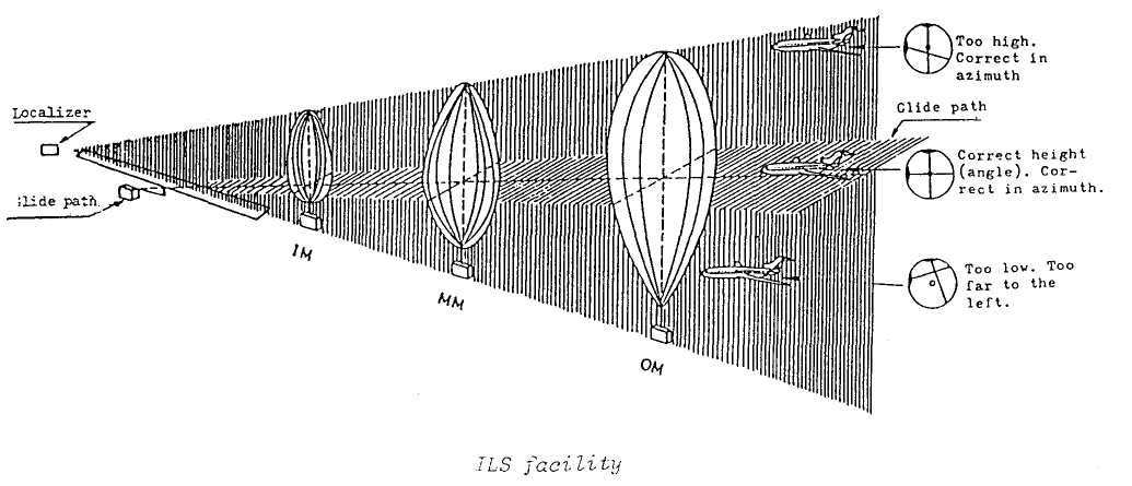
In addition to the ILS localizer and glide path, an ILS installation also comprises two or three fan markers: one called the outer marker is situated from four to six miles from the threshold of the runway; a second called the middle marker is situated approximately half a mile from the threshold of the runway, and the third, called the inner marker (installed only when required) is about 1,000 feet from the threshold of the runway. These fan markers alert the pilot of his passing over these markers by causing a light on the aircraft instrument panel to flash on and off while he is over each marker.
install [in7stO:l]устанавливать
flash on and off мигать
TEXT 10
SOME PROBLEMS ASSOCIATED WITH RADAR (Part 1)
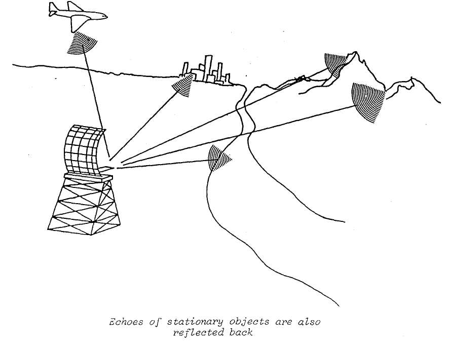
One of the problems associated with radar is the amount of unwanted clutter or the radar scope which the scanner picks up. This unwanted clutter is mainly echoes of stationary objects, such as mountains and other elevated terrain, as well as other objects situated close to the transmitting/receiving antennae.
With too much clutter, a controller cannot always see the aircraft. MTI allows him to reduce such clutter. The MTI does this by not allowing echoes received from stationary objects to be displayed on the radar scope. A controller has an MTI switch at his console and with this he can control, to a degree, the amount of clutter caused by stationary objects.
However, clutter is not caused by stationary objects only, echoes received from precipitation and/or clouds also cause clutter. MTI is effective in removing clutter caused by precipitation and clouds to a limited extent since MTI permits any echo which is moving to be displayed. So an additional technique known as Circular Polarization has been developed which prevents the display of most of the clutter caused by precipitation and clouds.
clutter [klVtE]помехи
MTI moving target indicator индикатор движущей цели
circular [7sE:kjulE]круговой
TEXT 11
OTHER NAVIGATIONAL AIDS
We have seen, in previous lessons, how VOR/DME/ILS work. However, we have not yet discussed Direction Finding which is one of the oldest methods of navigation. Direction Finding originally was developed in the 1920s to provide a "fix" on an aircraft's position. Generally speaking, this is an emergency type of navigational device which enables a controller to help a "lost" pilot find an airport by giving him headings to follow. The technique is useful on occasions in search and rescue operations to plot the location of an aircraft at an unknown position.
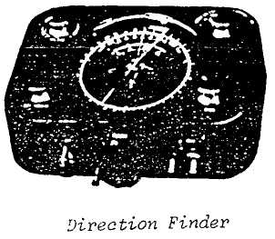
Automatic direction finding (ADF) is an airborne counterpart of the ground Direction Finding equipment. In an aircraft, the ADF permits a pilot to take continuous bearings automatically on any ground station operating on a frequency usable by the airborne equipment. The ground stations which are available to the pilot for this purpose include "compass locators", Non-directional Radio Beacon (NDB), and commercial radio-broadcasting stations. All of these may be used by the ADF-equipped aircraft for en-route navigation and for approaches to certain airports in remote areas. ADF is used mainly as a "backup" navigational device, or in areas of the world where traffic is light and ground navigation aids are limited. It does not provide the position-fixing accuracy or display needed for modern air navigation in high-density traffic patterns.
There are other navigational aids: Decca and LORAN are two of the most commonly known in aviation.
counterpart [7kauntE7pa:t]партнёр, напарник
ADF пеленгация, пеленгатор
TEXT 12
THE CONTROL TOWER (Part 1)
The tower's ‘tools’ include a number of radio transmitters and receivers used to communicate with pilots, and a signalling lamp to send control signals to any aircraft not radio equipped or with a radio that is not properly working. The tower's radio equipment may be used with microphone and loudspeakers or with a headset. There is a wind speed indicator and a wind direction indicator at each controller console. A further instrument is the altimeter setting indicator. It is from this instrument that the controller advises the pilot of the current altimeter setting which the pilot sets on his aircraft altimeter.
At some busy airports an Automatic Terminal Information Service (ATIS) is available to pilots of departing and arriving aircraft. This service consists of a continuous radio broadcast on a special frequency of recorded and periodically updated noncontrol information. Included is information regarding ceiling, visibility, wind direction and speed, altimeter settings, and runway in use. Where ATIS is not available, the tower provides this information.
A controller has to decide which separation standard he will apply to aircraft in flight. If he applies lateral separation he must maintain aircraft on different routes or in different geographical areas-
In applying longitudinal separation the controller maintains an interval between aircraft. Longitudinal separation is established by requiring aircraft to depart at a specified time; to arrive over a reporting point at a specified time; or • hold over a reporting point until a specified time. A 15-minute, time-spacing interval. between two 600 mph jet aircraft means that they are separated longitudinally by 150 miles.
Vertical separation is obtained by assigning different flight levels to aircraft, in other words, they are separated by a specified vertical distance.
specified [7spesifaid]конкретно определённое