

-
Read and translate the text.
A transformer is an electrical device that transfers energy from one circuit to another by magnetic coupling, without requiring relative motion between its parts. A transformer comprises two or more coupled windings, and, in most cases, a magnetic core to concentrate magnetic flux. A changing voltage applied to one winding creates a time-varying magnetic flux in the core, which induces a voltage in the other windings.
The transformer is one of the simplest of electrical devices, yet transformer designs and materials continue to be improved.
Transformers come in a range of sizes from a thumbnail-sized coupling transformer hidden inside a stage microphone to huge gigawatt units used to interconnect large portions of national power grids. All operate with the same basic principles and with many similarities in their parts.
Michael Faraday built the first transformer in 1831, although he used it only to demonstrate the principle of electromagnetic induction and did not foresee its practical uses.
Coupling by mutual induction The principles of the transformer are illustrated by consideration of a hypothetical ideal transformer. In this case, the core requires negligible magnemotive force to sustain flux, and all flux linking the primary winding also links the secondary winding. The hypothetical ideal transformer has no resistance in its coils. A simple transformer consists of two electrical conductors called the primary winding and the secondary winding. Energy is coupled between the windings by the time varying magnetic flux that passes through (links) both primary and secondary windings. Whenever the amount of current in a coil changes, a voltage is induced in the neighboring coil. The effect, called mutual inductance, is an example of electromagnetic induction.
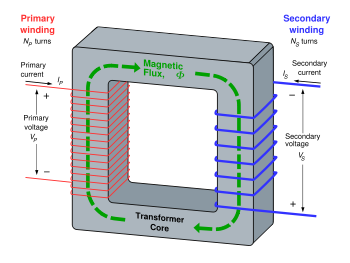
An ideal step-down transformer showing flux in the core
If a
time-varying voltage
![]() is
applied to the primary winding of
is
applied to the primary winding of
![]() turns,
a current will flow in it producing a magnetomotive force (MMF). Just
as an electromotive force (EMF) drives current around an electric
circuit, so MMF tries to drive magnetic flux through a magnetic
circuit. The primary MMF produces a varying magnetic flux
turns,
a current will flow in it producing a magnetomotive force (MMF). Just
as an electromotive force (EMF) drives current around an electric
circuit, so MMF tries to drive magnetic flux through a magnetic
circuit. The primary MMF produces a varying magnetic flux
![]() in
the core, and, with an open circuit secondary winding, induces a back
electromotive force (EMF) in opposition to
in
the core, and, with an open circuit secondary winding, induces a back
electromotive force (EMF) in opposition to
![]() .
In accordance with Faraday's law of induction, the voltage induced
across the primary winding is proportional to the rate of change of
flux:
.
In accordance with Faraday's law of induction, the voltage induced
across the primary winding is proportional to the rate of change of
flux:
![]() and
and ![]()
where
-
vP and vS are the voltages across the primary winding and secondary winding,
-
NP and NS are the numbers of turns in the primary winding and secondary winding,
dΦP / dt and dΦS / dt are the derivatives of the flux with respect to time of the primary and secondary windings.
In the
hypothetical ideal transformer, the primary and secondary windings
are perfectly coupled, or equivalently,
![]() .
Substituting and solving for the voltages shows that:
.
Substituting and solving for the voltages shows that:
![]()
where
-
vp and vs are voltages across primary and secondary,
-
Np and Ns are the numbers of turns in the primary and secondary, respectively.
Hence in an ideal transformer, the ratio of the primary and secondary voltages is equal to the ratio of the number of turns in their windings, or alternatively, the voltage per turn is the same for both windings. The ratio of the currents in the primary and secondary circuits is inversely proportional to the turns ratio.
The EMF in the secondary winding will cause current to flow in a secondary circuit. The MMF produced by current in the secondary winding opposes the MMF of the primary winding and so tends to cancel the flux in the core. Since the reduced flux reduces the EMF induced in the primary winding, increased current flows in the primary circuit. The resulting increase in MMF due to the primary current offsets the effect of the opposing secondary MMF. In this way, the electrical energy fed into the primary winding is delivered to the secondary winding. In addition, the flux density will always stay the same as long as the primary voltage is steady.
For example, suppose a power of 50 watts is supplied to a resistive load from a transformer with a turns ratio of 25:2.
-
P = EI (power = electromotive force × current)
50 W = 2 V × 25 A in the primary circuit if the load is a resistive load. (See note 1)
-
Now with transformer change:
50 W = 25 V × 2 A in the secondary circuit.
Since a direct current by definition does not change, it produces a steady MMF and so steady flux in the core; this quantity does not change and so cannot induce a voltage in the secondary winding. In a practical transformer, direct current applied to the winding will create only heat.