

StrokeOrNot
.pdfSUMMARY
This white paper presents a mathematical analysis of the piston dynamics of three popular versions of the Mitsubishi 4G63 engine, the stock 2.0L, the 2.1L destroked version with an 88mm crankshaft in a 4G64 block, and the stroker with a 100 mm crankshaft in a 4G63 block. Where applicable, charts are included to show the differences between the versions at different RPM’s or different crank angles.
The conventional wisdom that strokers make more torque but the 2.0L will rev higher is explained with hard calculations of such factors as piston side loading friction and tension on the rods. The 2.3L stroker has the same side loading friction at 7150 RPM as the 2.0L at 8000 RPM.
The conventional wisdom that the vibration from removing balance shafts is less than the effect of mismatched piston weights is challenged and explained with a mathematical analysis. A 2.3L stroker has the same harmonic imbalance at 7040 RPM as the 2.0L at 8000 RPM.
The effect of the stroker geometry on camshaft selection is examined and supported with charts of common aftermarket 4G63 cams. The analysis shows that stroker engines are more tolerant of aggressive cams than the stock engine. The intake velocity of a stroker at 7000 RPM is the same as a 2.0L at 8000 RPM. Peak piston velocity of a stroker at 7390 RPM is the same as a 2.0L at 8000 RPM.
INTRODUCTION
After spending too many hours researching how to make my 1998 AWD Talon even better than new including reading many tuner posts in the DSM forums I decided to create this document as a payback to the DSM community.
The scope of this document is limited to the differences between common versions of the Mitsubishi 4G63 engine. The calculations are directed toward answering the question “should I stroke my 4G63 or not”.
All equations used in this document are documented in Appendix A. The charts are print outs from an Excel project. The Excel file is available as described in Appendix A.
This document was drafted by Maurice Garoutte for the use of the DSM community and is not copyrighted. This document ended up longer and more technical than first planned but for readers who want more please follow the references.
Disclaimer
THIS DOCUMENT IS FOR THE ENTERTAINMENT AND POSSIBLE EDIFICATION OF THE DSM COMMUNITY ONLY. NO 4G63 ENGINES WERE HARMED FOR THE PRODUCTION OF THIS DOCUMENT. DON’T TRY THIS AT HOME. THE USE OR ABUSE OF THE INFORMATION HAS NO WARRANTY EITHER EXPRESS OR IMPLIED. THE AUTHORS LIBILITY FOR THE CONTENT OF THIS DOCUMENT SHALL NOT EXCEED THE PAYMENT FOR THE DOCUMENT, NOTA, ZERO BUCKS. IF YOUR 4G63 THROWS CHUNKS AT 10,000 RPM AFTER READING THIS, DON’T COME CRYING TO ME. YOUR MILAGE MAY VARY. THE OPINIONS EXPRESSED HERE MAY NOT REPRESENT THE OPINION OF THE MANAGEMENT. MANAGEMENT?
TABLE OF CONTENTS |
|
SUMMARY ........................................................................................................................ |
1 |
INTRODUCTION............................................................................................................... |
2 |
Disclaimer ....................................................................................................................... |
2 |
TABLE OF CONTENTS.................................................................................................... |
3 |
LIST OF FIGURES............................................................................................................. |
4 |
POWER vs. TORQUE........................................................................................................ |
5 |
Intake limitations............................................................................................................. |
5 |
Bigger Valves Needs Bigger Bore .................................................................................. |
7 |
Conversion of Pressure to Torque................................................................................... |
7 |
Boost is Good.................................................................................................................. |
9 |
Heat of Compression....................................................................................................... |
9 |
RPM LIMITATIONS OF STROKERS............................................................................ |
11 |
Piston Speed.................................................................................................................. |
11 |
Rod Tension .................................................................................................................. |
13 |
Friction Losses .............................................................................................................. |
15 |
WHATS AN “IDEAL” ROD RATIO............................................................................... |
20 |
STROKERS AND ENGINE BALANCE......................................................................... |
22 |
Imbalance in Pounds ..................................................................................................... |
22 |
Imbalance from Mismatched Parts................................................................................ |
23 |
STROKE AND CAM SELECTION................................................................................. |
26 |
Displacement................................................................................................................. |
26 |
Piston Velocity.............................................................................................................. |
27 |
Rod Ratio and Piston Velocity...................................................................................... |
28 |
Longer Stroke and Lower Rod Ratio ............................................................................ |
30 |
Effective Compression Ratio ........................................................................................ |
31 |
Effect of Cam Profile on ECR................................................................................... |
32 |
Effect of Rod Ratio on ECR...................................................................................... |
33 |
Rod Ratio and Stroke Effect on Overlap................................................................... |
34 |
ROD RATIO STROKERS AND ROD SELECTION...................................................... |
36 |
STROKER’S AND PISTON SELECTION...................................................................... |
37 |
ROD RATIO AND IGNITION TIMING......................................................................... |
39 |
HARMONIC BALANCE OF IN LINE FOURS.............................................................. |
41 |
CONCLUSIONS............................................................................................................... |
44 |
2.3L Stroker Pros........................................................................................................... |
44 |
2.3L Stroker Cons ......................................................................................................... |
44 |
Summary of Calculations.............................................................................................. |
45 |
RECOMMENDATIONS .................................................................................................. |
46 |
REFERENCES.................................................................................................................. |
47 |
APPENDIX A – FORMULA USED IN CHARTS .......................................................... |
51 |
APPENDIX C - DEFINITIONS ....................................................................................... |
55 |
LIST OF FIGURES |
|
Figure 1 Hemispherical Combustion Chamber................................................................... |
5 |
Figure 2 4G63 Combustion Chamber ................................................................................. |
6 |
Figure 3 Leverage on the Crankshaft .................................................................................. |
7 |
Figure 4 Cylinder Pressure to Torque Conversion.............................................................. |
8 |
Figure 5 V-1710 Allison Engine......................................................................................... |
9 |
Figure 6 Piston Velocity at 8000 RPM ............................................................................. |
11 |
Figure 7 Peak Piston Acceleration 4G63 Versions........................................................... |
12 |
Figure 8 Rod Failure in Tension ....................................................................................... |
13 |
Figure 9 Gratuitous Image................................................................................................. |
13 |
Figure 10 Rod Failure in Compression ............................................................................ |
13 |
Figure 11 Force on Rods by Crank Angle......................................................................... |
14 |
Figure 12 Peak Force on Rods by RPM............................................................................ |
15 |
Figure 13 Side Load Friction Components – 2.0L............................................................ |
17 |
Figure 14 Side Load Friction by RPM.............................................................................. |
18 |
Figure 15 Side Load Friction Components – 2.3L............................................................ |
19 |
Figure 16 Piston Acceleration 4 Rod Angles.................................................................... |
20 |
Figure 17 Piston Acceleration 4 Rod Ratios..................................................................... |
21 |
Figure 18 Piston Acceleration 4G63 Versions.................................................................. |
22 |
Figure 19 Harmonic Imbalance 4G63 Versions................................................................ |
23 |
Figure 20 Balance Forces for 2.0L 8000 RPM ................................................................. |
24 |
Figure 21 Balance Forces for Stroker 8000 RPM............................................................. |
24 |
Figure 22 Balance Forces for Stroker 4000 RPM............................................................. |
25 |
Figure 23 Displacement vs. Crank Angle ......................................................................... |
27 |
Figure 24 Piston Velocity 4G63 Versions ........................................................................ |
28 |
Figure 25 Peak Piston Velocity vs. Rod Ratio.................................................................. |
29 |
Figure 26 Mid Stroke vs. Rod Ratio ................................................................................ |
30 |
Figure 27 Piston Velocities 3 Rod Ratios and Stroker..................................................... |
31 |
Figure 28 Cam Timing and ECR ...................................................................................... |
32 |
Figure 29 Rod Ratio and ECR........................................................................................... |
33 |
Figure 30 Valve Overlap 4G63 Versions.......................................................................... |
34 |
Figure 31 Torque Conversion at Max Pressure................................................................. |
40 |
Figure 32 Piston Acceleration at 8000 RPM..................................................................... |
41 |
Figure 33 Harmonic Imbalance 4G63 Versions................................................................ |
42 |
Figure 34 Mitsubishi Silent Shafts.................................................................................... |
42 |
POWER vs. TORQUE
A quick search finds 1300 pages on dsmtuners.com site with the words stroker OR 2.3L AND torque. That topic is a thoroughly beaten, very dead horse. Without reading all of those pages, it’s clear that the conventional wisdom is that the stroker makes more low end/mid range torque but not necessarily more power. That old saw is pretty much true and this paper is focused on the differences in the two versions, not on which is “better”.
The next section of this paper is concerned with the RPM limitations of the stroker. Before getting into the limitations of the stroker version of the 4G63, the horsepower limitations of the 4G63 are examined here. This is pretty much
basic engine theory so feel free to skip to the next section.
Intake limitations
The 4G63 is a strong engine capable of handling much more horsepower than the factory spec. Regardless of how strong the parts, engines making power just from air and gasoline are limited by how much air can get into the combustion chamber. Boost is good. A charge with two bar of boost can burn twice as much fuel as one bar.
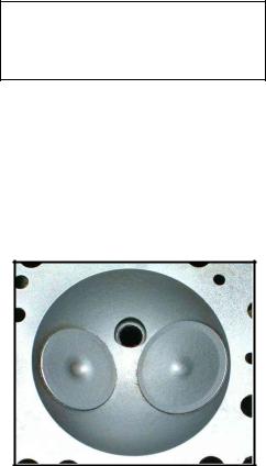
For any boost level the limit of how much air can enter the combustion chamber is limited by the intake tract and the size of the intake valves. Back when the author put a 1951 hemi engine in a 1948 Plymouth coupe the hemispherical combustion chamber was state-of-the-art in car engines. See figure 1 at right. Back in 1951 those were some really big valves, angling the valves in from each side allowed bigger valves while a center mounted plug improved flame propagation.
Figure 1 Hemispherical Combustion
Chamber
Bigger valves are a good thing because we can’t just make the air go faster. When air flow reaches mach one (equal to the local speed of sound) the flow is “choked” increasing the pressure drop across the valve just puts more energy in shock waves but the air flow does not increase. According to the Mechanical Engineers Handbook (19) engines have the best volumetric efficiency with a mach index of 0.45 to 0.5. While a mach index of 1 is a hard wall, the choking effect from high mach flow starts about 0.6. Above a mach index of 0.6 the volumetric efficiency of any engines falls off rapidly.
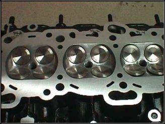
The state-of-the-art in car engines is now four valves per cylinder with overhead cams as in the 4G63 pent roof engine. See figure 2 at right and compare to the Hemi combustion chamber above. Notice how the two large valves in the hemispherical chamber leave much of the combustion chamber as “not valves”. The pent roof design modifies the hemi just enough to fit two more valves in the combustion leaving little area that is not filled with valves.
A lot has changed. That 1951 hemi weighed in at 960 pounds and made 180 hp at 4000 RPM from its 331 cubic inches. With a few bolt on modifications the 122 cubic inch 4G63 easily makes 400 hp at 8000 RPM while weighing in at only 300 pounds.
But the speed of sound is still the same as in1951. The hemi has an intake valve mach index of 0.51 at the 4000 RPM where max hp is developed. The 4G63 has the same .51 intake valve mach index at 8000 RPM. When the 4G63 reaches the mach index of .51 it’s turning twice as fast as the hemi and with 15 pounds of boost is breathing more than twice as many pounds of air than the 331 hemi at 4000 RPM. Boost is good.
Aside from the history lesson, the message I get from this is that no matter how strong the main caps, or how well designed the pistons, there is a hard performance wall where the intake velocity approaches sonic flow through the valves. The 2.0L 4g63 with stock valves reaches 0.6 mach index at 9600 RPM. The 2.3L stroker reaches 0.6 mach index at 8400 RPM. Trying to spin the 2.3L stroker much past 8400 RPM will just hit the wall quicker as volumetric efficiency drops off. The theory seems to hold up to a check of the top eight DSM’s on pump gas (Ludachris and anyone making more power) on http://www.dsmtuners.com/forums/dynosheets.php?&do=pumpgas. The table below shows that three of the eight are 2.0L engines, only Armandovivoni used nitrous.
Table 1 Horsepower Leaders on Pump Gas
Rank |
User |
HP |
Type |
Rank |
User |
HP |
Type |
1 |
Armandovivoni |
541 |
2.0L |
5 |
nanokpsi |
501 |
2.4L |
2 |
Super95awd |
521 |
2.3L |
6 |
FFTEC |
477 |
2.0L |
3 |
greentrbo_95gst |
513 |
2.3L |
7 |
GreddyGST |
445 |
2.0L |
4 |
Mitsutalon |
503 |
2.3L |
8 |
Ludachris |
434 |
2.3L |

Bigger Valves Needs Bigger Bore
Where an engine like the 4G63 is limited by the flow through the valves, making the stroke longer will not make much more power. The pent roof head is already full of valves. To get bigger valves the bore has to be bigger. But that’s not an option for the DSM world, just another old saw that still cuts.
Conversion of Pressure to Torque
Some of the papers researched for this paper mention that longer rods have better leverage on the crankshaft for a longer time (11).
However, for the top of the power stroke where most of the power is made, the shorter rod ratio, and the longer stroke have better leverage on the crankshaft to turn cylinder pressure into torque.
Figure 3 at right depicts two exaggerated examples, one of a short rod, long stroke and one long rod short stroke engine. The crank angle is the same for both examples. The heavy red lines are right angles from the alignment of the rod to intersect the center of the crankshaft. The length of the heavy red lines indicates the relative leverages on the crankshaft for any force from the piston. An interesting thing to notice here is that the side loading of the stroker motor is not all a bad thing. Think of it as the piston leaning on the
cylinder wall to get a better push on the
Figure 3 Leverage on the Crankshaft
crankshaft.
In the bottom half of the power stroke the higher rod angle of the stroker is the wrong direction and makes less torque for any given cylinder pressure. The good news for the stroker is that the cylinder pressure is less in the bottom half of the stroke by about the ratio of the static compression. For example, with a 10:1 static compression ratio the pressure at the bottom of the stroke will be less than 10% of the pressure at the top of the power stroke. The hotter the fuel burn the greater the pressure drop ratio as the temperature of the gas goes down.
Figure 4 below is a plot of the torque generated from a constant 100 pounds of force on the rod. Friction losses from side loading are neglected. The 100 pounds is held constant for the full power stroke to isolate the effect of the rod ration and stroke. The theoretical 2.3L engine with 1.7 rod ratio is included to isolate the effect of the rod ratio from longer
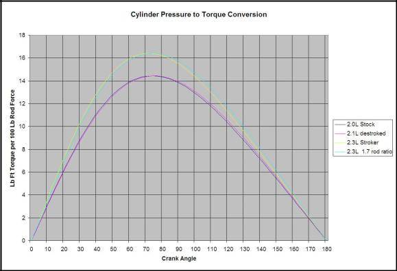
stroke of the 2.3L stroker. The plot shows pretty much what the exaggerated examples of Figure 3 above suggests. The longer stroke always has more torque than the shorter stroke. The shorter rods have more torque in the top half of the power stroke and the long rods have more torque in the bottom half.
Figure 4 Cylinder Pressure to Torque Conversion
Boost is Good
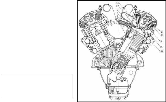
Well maybe a lot has changed, but the pent roof combustion chamber dates back to before WW II. Figure 5 below is a cross section drawing of a V-1710 Allison engine designed in the 1930s with overhead cams and four valves per cylinder in a pent roof combustion chamber.
The Allison engine powered the P38
Lighting and the early Mustang P51.
Later Mustangs were powered by the
Rolls Royce Merlin engine.
Both the Merlin and Allison engines were 27 liter V12 engines with 4 valves per cylinder. The Allison was more efficient and made more power at the same boost with its pent roof combustion chamber compared to the Merlin with its flat topped chamber.
Even with the superior pent roof combustion chamber the Allison lost out to the Merlin’s better boost design. Boost is good.
Figure 5 V-1710 Allison Engine
Even with the superior pent roof combustion chamber the Allison lost out to the Merlin’s better boost design. While the Allison had a single stage of turbo boost (Like the 4G63) the Merlin had two stages of supercharging with an intercooler between the stages and an aftercooler before the engine. The Merlin could also control boost from the cockpit taking full advantage of the higher octane fuel as it arrived from the U.S. Because of the better boost system the Merlin engine is legendary for winning the air war in Europe while the superior Allison design is known today as an upgrade engine in tractor pulling competition. Boost is good.
Heat of Compression
Removing the heat of compression is crucial to performance of the 4G63T. The effect of larger intercoolers is a regular topic in the DSM forums but heat of compression is seldom explained.
Basically, all of the work required to compress air goes into the air in the form of heat. Even with a 100 percent efficient compressor the compressed air will be at a higher temperature than it started. If air is compressed with a piston in a cylinder and the heat of
compression is not removed the final pressure will be more than the static compression ratio by an exponent of 1.4. This means that with a static compression of 10:1 the resulting pressure will increase by a factor of 10^1.4 or over 25:1 unless some of the heat of compression is removed. With a cold engine most of the heat of compression will be removed from contact with the block and piston and the pressure increase for a 10:1 engine will be “only” about 15 or 20 to one (30).
The table below is from a few quick calculations on the scratch pad of the spread sheet comparing the 8.5:1 CR 4G63 with the latest Corvette engine with 10.9:1 CR. The calculations based on the ideal gas laws shows that with a moderately effective intercooler a 4G63 with three bar of boost will have a lower charge temps than the normally aspirated small block with over twice the charge pressure.
Table 2 Effect of Heat of Compression
Condition |
Charge Temp |
Charge Pres |
|
Small Block 10.9:1 CR no boost |
948 |
402 |
|
4G63 |
8.5:1 CR 3 bar boost, intercooled |
816 |
867 |
4G63 |
8.5:1 CR 3 bar boost not intercooled |
1457 |
1354 |
The Corvette Z06 engine with the 10.9:1 CR is on the ragged edge of detonation with 93 octane fuel. Higher charge temps or lower octane will cause destructive detonation. The condition of the 4G63 without an intercooler shows the effect of trying to run 25.5:1 CR (3 * 8.5) without removing the heat of compression Boost is good, but only with a working intercooler.
The 4G63 is a turbo engine, not an engine with an added turbo. In the original 2.0L size my Talon was gutless until the turbo spooled. And in the mountains it could barely get out of its own way while off boost. Although mostly ignored in this paper comparing the stroker to the 2.0L, the turbo and intercooler are integral to the engine design.