

StrokeOrNot
.pdfAPPENDIX A – FORMULA USED IN CHARTS
The Excel Worksheet used in this white paper is available from http://kidzuku.com\4G63PistonForces.zip. Please download and unzip for local use. The spreadsheet was not (NOT I say) prepared for commercial use. Some familiarity with the idiosyncrasies of Excel will be required to get results from the spreadsheet.
Basics for all calculations
|
Reference (17) |
|
|
2.0L |
|
2.1L |
|
2.3L |
|
|
|
Stroke mm |
S |
|
88 |
|
88 |
|
100 |
|
|
Bore mm |
B |
|
85 |
|
87 |
|
86 |
Connecting Rod Length (+/- 0.05mm) |
R |
|
150 |
|
162 |
|
150 |
||
Number of Cylinders |
N |
|
4 |
|
4 |
|
4 |
||
|
|
|
|
|
|
|
|
|
|
|
|
|
|
|
|
|
|
|
|
|
Rod Stroke ratio |
R/S |
|
1.70 |
|
1.84 |
|
1.5 |
|
|
|
|
|
|
|
|
|
|
|
Engine Displacement (cc) |
D*N |
|
1997 |
|
2092 |
|
2323 |
||
|
Crank Arm mm |
S/2 |
|
|
|
|
|
|
|
|
|
|
|
|
|
||||
RPM |
T |
Revolutions per minute of the Crank |
|
|
|
||||
Picton Velocity |
V |
This is the speed of the Piston's movement measured in |
|||||||
|
|
meters per second |
|
|
|
|
|
||
Piston |
A |
The rate of change in velocity, measured in meters per |
|
||||||
Acceleration |
|
second per second |
|
|
|
|
|
||
Crank Angle |
K |
Crank angle in degrees after TDC |
|
|
|
||||
To calculate the velocity (V) of the piston when the crank is at a particular degree of rotation (K) ATDC and at a given RPM (T) the formula is: (17)
Piston Velocity at a given crank angle
V=(T*ATAN(1)/7.5)*((S/2)/1000)*SIN(((ATAN(1)/7.5)*K/6))*(1+COS(((ATAN(1)/7.5)*K/6)) /(SQRT(((R/(S/2))^2)-SIN(((ATAN(1)/7.5)*K/6))*SIN(((ATAN(1)/7.5)*K/6)))))
The formula for calculating the acceleration rate (A) of a piston at a given crank angle after TDC (K) is (17)
Acceleration in Meters per second per second at K
=((T*ATAN(1)/7.5)^2)*((S/2)/1000)* ((1- COS(4*((ATAN(1)/7.5)*K/6)))/(8*(SQRT(((R/(S/2))^2)- SIN(((ATAN(1)/7.5)*K/6))*SIN(((ATAN(1)/7.5)*K/6)) ))^ 3)+COS(2*((ATAN(1)/7.5)*K/6))/(SQRT(((R/(S/2))^2)- SIN(((ATAN(1)/7.5)*K/6))*SIN(((ATAN(1)/7.5)*K/6)) ))+COS(((ATAN(1)/7.5)*K/6)))

The formula for the location (W) and displacement (D) of the piston for a given crank angle (K) after TDC is: (17)
Location = W = (((S/2)+R)-((S/2)*COS(RADIANS(K)))-SQRT(R^2- ((S/2)*SIN(RADIANS(K)))^2))
Displacement at K = D = (+PI()*(B^2)*W/1000)/4
To calculate the imbalance force in pounds and effective compression required a few more formula to be developed and tested.
Gs or G forces |
G |
Non-dimensional, 1 G = normal earth Gravity |
Force |
F |
Force in pounds |
Harmonic Imbalance |
HI |
Force due to harmonic imbalance in pounds |
Static Imbalance |
SI |
Force due to mismatched weights in pounds |
Total Imbalance |
TI |
Static Imbalance plus Harmonic Imbalance |
Reciprocating Mass |
RM |
Recip. mass in pounds (grams *0.0022046) |
Swept Volume |
SV |
Displacement of one cylinder (cc) |
Head Volume |
HV |
Volume of combustion chamber (cc) |
Static Compression Ratio |
CR |
Using full swept volume (SV + HV)/HV |
Compressed Volume |
CV |
Displacement at point of intake valve closing |
Uncompressed Volume |
UV |
Swept Volume – Compressed Volume |
Effective CR |
ECR |
Using compressed volume (CV + HV)/HV |
Boost Pressure |
BP |
Cylinder pressure as intake valve closes |
Intake valve closing angle |
KIC |
Crank angle where the intake valve closes |
Cylinder Pressure at K |
CPK |
Pressure at K in same units as Boost Pressure |
Gforces:
G= A/9.80665
Reciprocating Mass (10):
RM = PistonWeight + RodWeight/3
Force:
F = G * RM
Harmonic Imbalance:
HI = FK1 + FK2 Where the crank angle at FK1 is 180 degrees from the force calculation at FK2.
Total Imbalance:
TI = HIRM1 + HIRM2 where the Harmonic Imbalance calculations for HIRM1 and HIRM2 are the same except for the reciprocating mass, and the crank angles are 180 degrees apart.
Static Imbalance:
SI = TI – HI
Swept Volume:
SV = (PI()*((B/2)^2)*S/1000)
Head Volume:
HV = SV/CR
Static Compression Ratio:
CR = Entered value of static compression ration accounting for bore, stroke, and piston shape. The advertised CR is assumed to include a nominal .040 thick head gasket.
Compressed Volume:
CV = Displacement at K of KIC. (Compression starts at intake valve closing.)
Uncompressed Volume:
UV = SV - CV
Effective CR:
ECR = CV/HV
Boost Pressure:
BP = entered boost pressure PSI absolute where 14.7 = normally aspirated and 29.4 equals two bar. Cylinder pressure is corrected for PSI gauge, where two bar reads 14.7 PSIG.
Intake Valve Closing Angle:
KIC = From cam specification referenced to a K of 0 degrees = TDC A specification of 28 degrees ABDC is a KIC of 208. (ABDC + 180)
Cylinder Pressure at K:
CPK = (((CV + HV)/ (MIN(CV,DK) + HV))^1.23 * BP) – 14.7 Where:
DK = Displacement at crank angle K
The exponent of 1.23 accounts for heat of compression. Minus 14.7 corrects the absolute units back to gauge pressure.
To calculate rod angles and effective lever length to calculate the effect of rod angle on torque a few more formulas had to be developed.
Rod Angle |
RA |
Calcs in radians outputs in degrees |
Crank Angle |
CA |
Calcs in radians, outputs in degrees |
Rod Length |
RL |
In mm |
Stroke/2 |
SH |
Half of the stroke in mm |
Rod Journal Offset |
RJO |
Rod Journal offset from Centerline mm |
Effective Lever Length |
ELL |
Lever on Crank adj for CA and RA, feet |
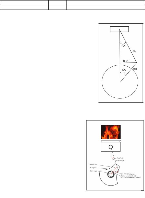
Rod Angle Formula
Sin CA = RJO/SH (Sin = Opp/Hyp)
RJO = SH * Sin CA
Sin RA = RJO/R (Sin = Opp/Hyp)
RA = ArcSin RJO/RL
RA = ArcSin((SH * Sin (CA))/RL)
Figure 35 Rod Angle Sketch
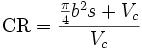
Effective Lever Length Formula
ELL = Cos(90 - RA + CA) * SH
Figure 36 Effective Lever Length
Sketch
APPENDIX A – SPECS USED IN THE CALCULATIONS
PUT THE ENGINE SIZES AND PISTON ROD SPECS HERE.
TALK ABOUT NO HARD DATA FOR 2.1L RODS.
APPENDIX C - DEFINITIONS
CAM OVERLAP (14): Refers to the time when both, the intake and exhaust valves of a given cylinder are open at the same time, measured in CAM DEGREES. Specifically, it is when the INTAKE valve begins to open, as the EXHAUST valve is just closing. The piston is still rising UP, chasing the exhaust valve closed, and the intake valve is opening to meet it. Increased overlap is needed on higher RPM's to provide additional time for the cylinder to "purge" itself of leftover gases from the prior combustion process. Physically, as explained in Lobe separation, the overlap cycle is the opposite perspective of the same consequence to cam design. They effect the engine's "running" compression ratio. You are merely saying the same thing from opposite perspectives. OVERLAP is a term not used much anymore, but was very much the perspective of cam development and comparison by professional engine builders during the pivotal cam development era of the late 1960's and 70's, where many of the breakthroughs of cam design were established. The transition to "lobe separation" lingo was the result of marketing by cam companies, beginning in the mid to late 1970's, who needed to boost cam sales and horsepower on LOW compression engines, resultant from the change in Detroit's gas guzzling car production, and ending the Muscle Car era as we knew it. Reduced CAM OVERLAP is INCREASED LOBE SEPARATION. This reduced cam overlap increased net effective cylinder pressure (NECP) within the engine, often boosting factory engine horsepower by in effect increasing the running compression on these milder, low compression engines. The greater OVERLAP was not needed on these low compression engines since they were not going to operate at high RPM's. Among advanced cam analysis in professional racing engines, cam overlap is still a critical perspective and term to be documented and used, particularly with cylinder head flow analysis.
NOTE: It is important to understand that you need to increase the static compression ratio of pistons (i.e., 9:1 up to 12:1) because a cam of greater overlap will lose "running compression" (NECP). Increasing the piston's compression ratio replaces this lost operating pressure from the increased cam overlap. (Assuming you have cylinder heads capable of breathing at these higher valve lifts and RPM's.) You cannot increase cam overlap and duration on a low compression engine without changing the pistons for higher static compression, and still achieve full potential. Nor can you install larger compression pistons without changing to a cam of higher overlap (and duration), since now you will have too much "running compression" (NECP) and likely burn pistons, valves and create other problems from excessive heat, pre-ignition and detonation. The two run hand in hand. The only exception to these necessities being chosen only for higher RPM operation would be a large cubic inch engine with a large stroke crankshaft; as this increased crank stroke increases piston velocity and increases airflow through the heads at lower RPM's.
Compression ratio(30)
The compression ratio is a single number that can be used to predict the performance of any engine (such as an internal-combustion engine or a Stirling Engine). It is a ratio between the volume of a combustion chamber and cylinder, when the piston is at the bottom of its stroke and the volume when the piston is at the top of its stroke. The higher the compression ratio, the more mechanical energy an engine can squeeze from its air-fuel mixture. Literally, high ratios place increased oxygen and fuel molecules into a reduced space, thus allowing for increased power at the moment of ignition. Higher compression ratios, however, also make detonation more likely.
The ratio is calculated by the following formula:
, where
b = cylinder bore (diameter)
s = piston stroke length
Vc = volume of the combustion chamber (including head gasket). This is the minimum volume of the space into which the fuel and air is compressed, prior to ignition. Because of the complex shape of this space, it usually is measured directly rather than calculated.
Due to pinging (detonation), the CR in a gasoline/petrol powered engine will usually not be much higher than 10:1, although some production automotive engines built for high-performance from 1955-1972 had compression ratios as high as 12.5:1, which could run safely on the high-octane leaded gasoline then available. Recently, with the addition of variable valve timing and knock sensors to delay ignition timing, one worldwide manufacturer is building 10.8 CR gasoline engines that use (U.S.) 87 octane fuel.
In engines running exclusively on LPG or CNG, the CR may be higher, due to the higher octane rating of these fuels.
IC racing engines burning methanol and ethanol often exceed a CR of 15:1.
In engines with a 'ping' or 'knock' sensor and an electronic control unit, the CR can be as high as 13:1 (2005 BMW K1200S)
In a turbocharged or supercharged engine, the CR is customarily built at 8.5:1 or lower.
In an auto-ignition diesel engine, the CR will customarily exceed 14:1--and over 22:1 is not uncommon.
Fault finding and diagnosis
Measuring the compression pressure of an engine, with a pressure gauge connected to the spark plug opening, gives an indication of the engine's state and quality.
If the nominal compression ratio of an engine is given, e.g. as 10:1, the measured pressure in each cylinder of common automotive designs can be roughly estimated in pounds per square inch as between 15 and 20 times the compression ratio, or in this case between 150 psi and 200 psi, depending on cam timing. Purpose-built racing engines, stationary engines etc. will return figures outside this range.
If there is a significant (> 10%) difference between cylinders, that may be an indication that valves or cylinder head gaskets are leaking, piston rings are worn or that the block is cracked.
If a problem is suspected then a more comprehensive test using a leak-down tester can locate the leak.
Because cylinder bore diameter, piston stroke length and combustion chamber volume are almost always constant, the compression ratio for a given engine is almost always constant, until engine wear takes its toll.
Dynamic Compression Ratio
The calculated compression ratio, as given above, presumes that the cylinder is sealed at the bottom of the stroke (BDC or bottom dead center), and that the volume compressed is the actual volume.
This is not true: intake valve closure (sealing the cylinder) always takes place after BDC, which causes some of the intake charge to be compressed backwards out of the cylinder by the rising piston at very low speeds; only the percentage of the stroke after intake valve closure is compressed. This "corrected" compression ratio is commonly called the "dynamic compression ratio".
This ratio is higher with more conservative (i.e., earlier, soon after BDC) intake cam timing, and lower with more radical (i.e., later, long after BDC) intake cam timing, but always lower than the static or "nominal" compression ratio. The actual position of the piston can be determined by trigonometry, using the stroke
length and the connecting rod length (measured between centers). The absolute cylinder pressure is the result of an exponent of the dynamic compression ratio. This exponent is a polytropic value for the ratio of variable heats for air and similar gases at the temperatures present. This compensates for the temperature rise caused by compression, as well as heat lost to the cylinder. Under ideal (adiabatic) conditions, the exponent would be 1.4, but a lower value, generally between 1.2 and 1.3 is used, since the amount of heat lost will vary among engines based on design, size and materials used, but provides useful results for purposes of comparison. For example, if the static compression ratio is 10:1, and the dynamic compression ratio is 7.5:1, a useful value for cylinder pressure would be (7.5)^1.3 × atmospheric pressure, or 13.727 × 14.7 psi at sea level, or 201.8 psi. The pressure shown on a gauge would be the absolute pressure less atmospheric pressure, or 187.1 psi. From this, we can see that the two corrections for dynamic compression ratio affect cylinder pressure in opposite directions, but not in equal strength. An engine with high static compression ratio and late intake valve closure will have a DCR similar to an engine with lower compression but earlier intake valve closure.
HORSEPOWER: (14) In its purest definition is: 1 HP= 33,000 Foot-Pounds of WORK Per Minute. In measurement, it is TORQUE multiplied by RPM divided by 5252. The essence of how horsepower is derived is based upon an understanding of the difference between WORK and TORQUE. FORCE is the common denominator of the two. WORK is DIRECT FORCE operating across a distance; while TORQUE is RADIAL FORCE operating around an axis. The formula of these is: POWER = FORCE x DISTANCE ÷ TIME. To calculate power, both DISTANCE and TIME must be derived, using FORCE across both of these. Where engines are involved, the rotational values of the crankshaft by its diameter is needed. To generate a formula for the TORQUE, the DISTANCE aspect is measured in RPM (revolutions per minute), times the RADIUS, times Pi (3.1416), times 2 (or 6.2832.). TORQUE is measured as Pounds of Force Times Distance. POWER is measured as FORCE times Distance per Minute. The 5252 value in our equation comes from 33,000 divided by 2x Pi (6.2832). Therefore: HP = Torque x RPM ÷ 5252. Something worth noting, is that at 5252 RPM, both TORQUE and HORSEPOWER will be equal. Beneath this value, Torque will be numerically greater, while above it Horsepower will be greater.
PISTON VELOCITY (14): This is a relatively self descriptive term, but its real influence with engine performance is often not fully understood. Piston velocity, or "speed," is the result of two things: (1) Crankshaft stroke, and (2) RPM's (obviously). Piston speed is THE SOURCE for response characteristics of cylinder head air flow through the ports, in addition to the cubic inch volume each cylinder has with every stroke. These are two crucial elements to place in proper context: (a) Airflow VOLUME, and (b) airflow VELOCITY. Cylinder volume in conjunction with piston speed determines all of the tuning characteristics and specification needs within a given cylinder head's design, as well as the fundamental camshaft specs to meet these needs. These two elements can offset each other when choosing cylinder head packages and/or camshafts. In other words, if you have a large cubic inch small block engine, its increased stroke will achieve high torque at lower RPM's compared to a conventional size small block engine, but it can use larger port heads and greater camshaft specs that would more typically be chosen for a high winding engine of smaller cubic inches.
NOTE: Torque is often the term that is used to explain what a large stroke engine sees. Although it is true that the operating pressures created with each power stroke is applying leverage onto a longer "arm" for an engine having a greater stroke, and thus "torque" forces upon the crank are increased, the simple truth with what is happening in the cylinder heads with airflow is that torque is a symptom from the increased PISTON VELOCITY that the stroke generated. The engine literally thinks it is going 8,000 RPM when the tach reads 6,800 RPM, because airflow and volume demand are greater at lower RPM's. There is a second dynamic to the piston's influence on the cylinder heads, dictated by a ratio of connecting rod length divided by crankshaft stroke. Known as the rod ratio this determines how quickly the STARTING and STOPPING of PISTON SPEED occurs. But the ultimate piston speed is still determined by our two main factors (crank stroke and RPM's). The formula for determining piston velocity in FPM (feet per minute) is this: STROKE x 3.1416 x RPM ÷ 12 = FPM. If you use this formula when comparing different engine strokes, you can see how the RPM's are affected. TO COMPARE, pick your first stroke combination and use the foregoing formula. Then save the FPM value in your calculator and begin working backwards from this sum. Only now substitute the division symbol for a multiplication symbol, and divide where there is a multiplication symbol. SKIP over the "RPM" in this second step working backwards while changing the STROKE value to your second choice (i.e., 4.50" first calculation compared to 4.00" for second comparison), and your final answer will be the different RPM "effect" created in the ports by the different stroke. The answer to a comparison of a 4.50" stroke running at 6,000 RPM, compared to a 4.00" stroke is 6,750 RPM. In other words two identical engines of the SAME SIZE cubic inches having their only difference being stroke, will have a 750 RPM increase being needed for the 4.00" stroke to have the same port velocity as the 4.50" stroke. Or more simply stated: the 4.50" stroke engine only needs to turn 6,000 RPM to make the same power that the 4.00" stroke engine can make at 6,750 RPM. When you consider that the stroked engine will also have more cubic inches (unless the cylinder bores were much smaller to keep the comparison the same size), the extra VOLUME dictates that PORT passages would also need to be increased, as well as VALVE LIFT. This is why it is easy to exceed the cylinder head capabilities when going into big stroke engines; not to mention all the increased work needed by larger induction and exhaust. When these limits are reached with such engines, the RPM's stop dead in their tracks, although you've created a "torque monster" at lower RPM's; and to think, it all starts with "piston velocity."
ROD RATIO (14) : Refers to the "connecting rods" between the piston and the crankshaft; but specifically, the mathematical division of a crankshaft's STROKE by the connecting rods LENGTH. Ranging anywhere from 1.3:1 (not good) to more than 2.0:1, the effects of rod ratio on an engine's performance and specifically its torque curve are significant. Rod ratio directly affects how the piston speed accelerates from its extreme positions of TDC and BDC (as well as slows down in approaching these points). The piston velocity still reaches its same peak value, as dictated by the crankshaft's stroke; but this acceleration toward this is determined by rod ratio, with the smaller values of rod ratio making these quicker, and the higher values slower, respectively. One distinct down side of lower rod ratios, is their inherently higher thrust of the piston's skirt into the cylinder wall. These require more piston skirt clearance compared to a similar stroke engine using a longer connecting rod. Of course, point of fact: if you have two engines of the same model with the same stroke, but different length connecting rods, then of course the difference must be made up with either a different Compression height piston, and/or a greater deck height block. It is commonly accepted that connecting rod ratios of 1.70:1 to 1.90:1 are preferred for most applications. Deviations above and below these values usually have some other negative offset. The higher the rod ratio, the higher the shift in RPM's for peak torque to occur.