

StrokeOrNot
.pdfFigure 27 Piston Velocities 3 Rod Ratios and
Stroker
The color keyed vertical lines in figure 28 mark the crank angles where the 2.3L and 2.0L stock versions reach peak piston velocity. Note that the 2.3L peak piston velocity is about 15 percent higher than stock and comes 2 degrees earlier. As long as the head and valves flow the air, the stroker will have more torque than the stock 2.0L.
Effective Compression Ratio
The compression ratio that is normally used discussing 4G63 specifications is the (30) Static Compression Ratio (SCR). SCR is simply the sum of displacement and head volume divided by head volume. SCR is a useful number because it doesn’t change with the camshaft profile. However in any real 4G63 version, the intake valve doesn’t close until several degrees after BDC. The delay in closing the intake valve allows the ram effect in the intake air stream to continue flowing air into the cylinder even while the piston is going up. (There’s that velocity effect again). The delay allows more air in the cylinder but compression can’t start until the intake valve closes. In any 4G63 version there will be some uncompressed volume because the piston is not at the bottom of the stroke when compression starts. The term Dynamic Compression Ratio (5) is often used for the compression that happens from the time the intake valve closes to piston TDC. However piston position at the valve closing event does not change with engine operating

conditions so this paper will use the less popular term of Effective Compression Ratio (ECR). ECR is affected by the cam profile and the rod ratio. At lower RPM’s air is forced back up the intake tract through the open intake valve as the piston moves up. At higher RPM’s the velocity of the intake stream still has air going into the cylinder as the intake valve closes. Peak torque occurs about the point where the air stream is just stopping as the intake valve closes. At higher RPM’s the volumetric efficiency starts to drop off as the cylinder does not get the full charge of air.
Effect of Cam Profile on ECR
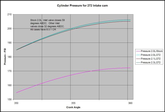
High performance cams delay the closing of the intake valve to get more power at higher RPM’s, raising the point of peak torque. The obvious trade off is lower ECR and less low end torque for higher performance cams. Figure 28 below shows the cylinder pressure vs. piston position for the stock cam, and HKS 264, and 272 cams. The 264 and 272 pressures are so close together that only one line shows, but the difference from the stock cam is clearly shown.
Figure 28 Cam Timing and ECR
Some posts on the DSM forums show the 2G stock intake cam closing 51 degrees ABDC but this paper uses 59 degrees according to the overhaul manual (29). (After production of these charts another “reliable” document was found showing differing cam timing for different codes as listed in the specifications section. Either way the stock intake cam stays open significantly longer than the two popular HKS cams.)
Effect of Rod Ratio on ECR
With lower rod ratios such as the 2.3L stroker the pistons move slower at the bottom of the stroke so have less uncompressed volume when the intake valve closes. Figure 29 below is zoomed in to near TDC to show that with the 272 cams and 8.5:1 SCR the 1.5 rod ratio of the 2.3L stroker has about 1 percent higher cylinder pressure than the 2.1L destroked version. The bottom, magenta, line is for the stock cam and 8.5:1 SCR.
Figure 29 shows that the lower rod ratios do have a higher ECR, but that the effect is small.
Figure 29 Rod Ratio and ECR
The Differences in ECR for three cams and three 4G63 Versions are summarized in Table 4 below. Note that the differences between cam profiles is larger than differences between rod ratios.
Table 3 Cam and Rod Ratio vs. ECR
4G63 Version |
2.0 L |
|
2.1L |
|
2.3L |
|
|
UV |
ECR |
UV |
ECR |
UV |
ECR |
Stock Cam (59o) 8.5 CR |
93.7 |
6.90 |
100.4 |
6.87 |
104.5 |
6.97 |
264 Cam (28o) 8.5 CR |
21.1 |
8.14 |
22.7 |
8.13 |
23.3 |
8.16 |
272 Cam (32o) 8.5 CR |
27.6 |
8.03 |
29.7 |
8.02 |
30.4 |
8.05 |
Rod Ratio and Stroke Effect on Overlap
The effect of rod ratio on piston position is mentioned in six of the references for this paper (5,6,8,11,16, and 17) so it must be a real factor. Right? The paper from GrapeApeRacing (11) was kind enough to call the effect “small”.
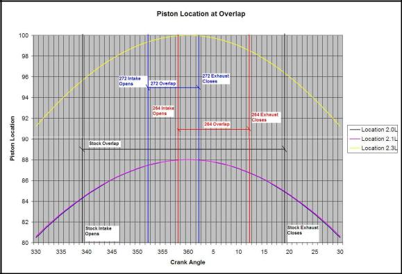
To show the effect of rod ratio on the period of valve overlap, crank position from 30 degrees before TDC to 30 degrees after TDC was charted in figure xx below. The valve events of intake valve opening and exhaust valve closing were added to the chart for stock 2G cams, HKS 264, and HKS 272 cams. The valve overlap area was then marked for each of the three cam sets. The chart is a little busy but helps us visualize the cam events better than raw numbers in a table.
Figure 30 Valve Overlap 4G63 Versions
Figure 30 clearly shows that the rod ratio difference between the stock 2.0L and the 2.1L destroked version is too small to affect cam selection. The 2.1L piston is moving slower than the 2.0 just as the theory says, but the two curves are almost on top of each other.
Equally clear from figure 30 is that the 2.3L stroker piston locations and speeds are significantly different from the stock 2.0L. Where the stock piston with the stock cam
moves up 3.5mm after the intake valve opens, the stroker piston moves up about 4.3mm. That’s about 20% more piston motion (and flow). Cam theory is beyond this author but it looks to me that the 2.3L stroker will respond to cam changes like the 2.0L but at a much lower RPM.
ROD RATIO STROKERS AND ROD SELECTION
Stroking the 4G63 changes the nature of the engine in the direction of more torque at lower RPM. The best trade off between connecting rod strengths in compression and tension for a high revving drag engine may not be the best for the 2.3L. The 2.3L stroker’s lower rod ratio increases the bending load on the rods due to the higher rod angle. The table below shows that the 2.3L will have about 14 percent more of the total compression load as bending force.
Table 4 Forces on Rods
Condition |
2.0L |
2.1L |
2.3L |
Maximum rod angle at 90 degrees crank angle |
16.8 |
15.6 |
19.1 |
Sin of maximum rod angle |
.2933 |
.2716 |
.33333 |
Percent of stock rod bending force |
100% |
92.6% |
113.6% |
Considerations for rod selection for the 2.3L include:
1.Since the 2.3L stroker will generate more torque but not rev as high as the 2.0L 4G63 connecting rods need to be designed in favor of withstanding compression loads.
2.The 2.3L stroker has a greater rod angle than the stocker causing more bending force on the rods than the 2.0L calling for rods designed to withstand bending forces.
3.The lower rod ratio and longer stroke of the 2.3L increase the inertial loads on the rods at any RPM calling for light weight rods.
The strength of a rod in tension is mostly determined by it’s cross sectional area, not the shape. All else being equal, heavier rods are stronger in tension. Resistance to bending force is more strongly influenced by shape. For equal weight, the H beam rod will handle more bending force. The V8 hot rodders have been using H beam rods for years as upgrades. (11)
The old saw still applies. Lighter rods are better until they break, then heavier rods would have been better.
STROKER’S AND PISTON SELECTION
The 2.3L stroker version of the 4G63 makes different demands on pistons from the stock 2.0L.
1.The stroker’s higher piston velocity and increased side loading increases the wear on pistons.
2.The lower rod ratio makes the stroker more sensitive to piston slap.
3.The higher piston acceleration rate makes the stroker more sensitive to piston weight.
4.The greater displacement and torque of the stroker puts more stress on the piston than the stock 2.0L. (All else being equal of course.)
Piston selection requires a compromise between the four items above to match the intended purpose of the engine.
Only forged pistons are considered here. The use of forged pistons is all to the good as they are both lighter and stronger than cast pistons. Forged pistons are mostly made from two Aluminum alloys with different silicon content, 4032 and 2618. The table below shows some of the key differences in the two alloys. Most of the data is from reference (32).
Table 5 Piston Material Properties
Property |
2618 |
4032 |
Percent Silicon |
<2% |
11% |
Density |
0.10 lb/in3 |
.097 lb/in3 |
Tensile Strength, Yield |
54,000 psi |
46,000 psi |
Modulus of Elasticity |
10,400 psi |
11,400 psi |
Fatigue Endurance Limit |
18,000 psi |
16,000 psi |
Coefficient of Thermal Expansion 68 to 572 degrees F |
13.4 uin/in/oF |
11.7 uin/in/oF |
Because 2618 expands more than 4032, piston to wall clearance for the 2618 piston has to be larger to have the same running clearance at operating temperature. On cold start up the 2618 piston can be expected to have more piston slap than the 4032 piston. Piston slap can be expected to be greater for the 2.3L stroker and slightly less for the 2.1L than for the stock engine.
Pistons forged from 2618 alloy have higher tensile strength and higher fatigue limits than 4032 and are better able to handle the additional stress of higher boost and occasional detonation. Because 2618 pistons are often designed for higher stress, they may be heavier than 4032 pistons.
Pistons forged from 4032 alloy will wear less than the 2618 pistons because the silicon makes the alloy harder. However being harder also means being more brittle. Failure in
a 4032 alloy piston is more likely to be catastrophic, while a 2618 piston may have a “partial” failure. (31)
Pistons forged from 4032 will wear better, probably be lighter and have less “piston slap” than 2618 pistons. The same old saw is still true. 4032 pistons are better, until they break then 2618 would have been better.
ROD RATIO AND IGNITION TIMING
When ignition timing is just right the spark plug fires long enough Before Top Dead Center (BTDC) so that the burning fuel/air reaches maximum combustion pressure about 15 to 20 degrees After Top Dead Center (ATDC) where the piston has started down and there is enough leverage on the crankshaft to turn the pressure into torque. If maximum pressure is too early the piston and rod can’t go down, however detonation can make at least the top of the piston go down. If maximum pressure is too late, it’s also too low and power is lost. (35,36)
Getting the maximum cylinder pressure to arrive at just the right time is a major goal of tuning. Some of the tuning variables affecting ignition timing are: (36)
1.Higher RPM needs more degrees advance for the same time for the flame front to expand to maximum.
2.Higher boost pressure causes the flame front to move faster.
3.Richer fuel/air mixture causes the flame front to move slower.
4.Higher octane fuel causes the flame front to move slower.
5.Higher cylinder temperatures are more likely to cause auto-ignition.
6.Higher octane fuel tolerates higher temperatures without auto-ignition.
7.Peaks closer to TDC are higher and more likely to cause detonation.
8.Peaks after optimum ATDC are less likely to knock and make less power.
The longer stroke and lower rod ratio of the 2.3L stroker has higher velocity ATDC and reaches the point where pressure can be converted to torque 2.25 degrees sooner than the 2.0L engine. Theoretically the stroker should tolerate more ignition timing advance (or lower octane) better than the stock 4G63.
Figure 31 below is a plot of the Lb Ft of torque developed for each 100 pounds of piston pressure zoomed in to the area where maximum cylinder pressure is reached. The red line highlights how much earlier the stroker reaches the same leverage on the crankshaft as the stock engine. Note that the longer rod ratio of the 2.1L causes that same leverage to be reached slightly later.
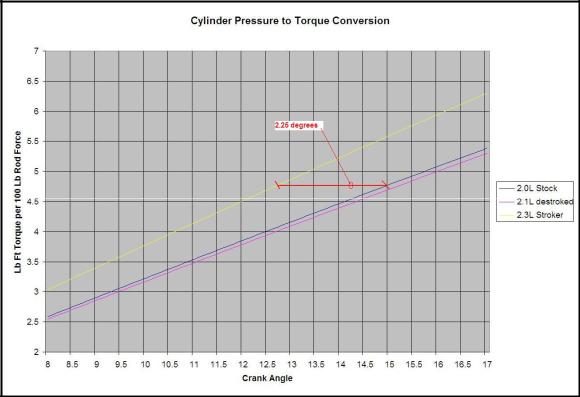
Figure 31 Torque Conversion at Max Pressure