

4.3 Point defects – zero- dimensional imperfections
Structural defects exist in real materials independently of chemical impurities. Imperfections associated with the crystalline point lattice are called point defects. Fig. 4.8 illustrates the 2 common types of point defects associated with elemental solids:
(1) The vacancy is simply an unoccupied atom site in the crystal structure.
(2) The interstitial, or interstitialcy, is an atom occupying an interstitial site not normally occupied by an atom in the perfect crystal structure or an extra atom inserted into the perfect crystal structure such that 2 atoms occupy positions close to a singly occupied atomic site in the perfect structure.
In the preceding section we saw how vacancies can be produced in compounds as a response to chemical impurities and nonstoichiometric compositions.
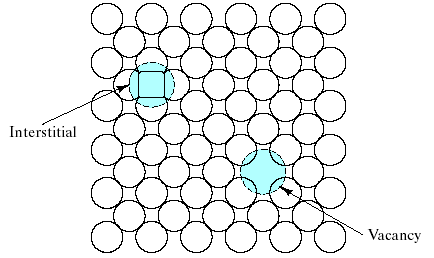
Fig.4.8 Two common point defects in metal or elemental semiconductor structures are the vacancy and the interstitial.
Such vacancies can also occur independently of these chemical factors (e.g., by the thermal vibration of atoms in a solid above a temperature of absolute zero). Fig. 4.9 illustrates 2 analogs of the vacancy and interstitialcy for compounds.
The Schottky defect is a pair of oppositely charged ion vacancies. This pairing is required in order to maintain local charge neutrality in the compound’s crystal structure. The Frenkel defect is a vacancy – interstitialcy combination. Most of the compound crystal structures were too “tight” to allow Frenkel defect formation.
Remember: CaF2 – type structure can accommodate cation interstitials without excessively lattice strain. Charging due to “electron trapping “or” electron hole trapping” at these lattice imperfections can further complicate defect structures in compounds.
4.4 Linear defects, or dislocations – one-dimensional imperfection
We have seen that point (zero-dimensional) defects are structural imperfections resulting from thermal agitation.
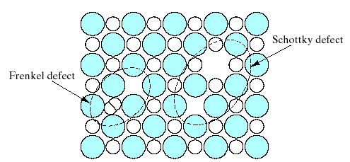
Fig.4.9. Two common point defect structures in compound structures are the Schottky defect and the Frenkel defect. Note their similarity
to the structures of Fig.4.8.
Linear defects, which are one-dimensional, are associated primarily with mechanical deformation. Linear defects are also known as dislocations. An especially simple example is shown in Fig. 4.10.
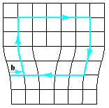
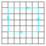
The linear defect is commonly designated by the “inverted T” symbol (), which represents the edge of an extra half-plane of atoms. Such a configuration lends itself to a simple quantitative designation, Burgers vector, b. This parameter is simply the displacement vector necessary to close a stepwise loop around the defect. In the perfect crystal Fig. 4.11a, an m x n atomic step loop closes at the starting point. In the region of a dislocation (Fig.4.11b), the same loop fails to close.
The closure vector (b) represents the magnitude of the structural defect. Fig. 4.10 represents a specific type of linear defect, the edge dislocation, so named because the defect, or dislocation line, runs along the edge of the extra row of atoms.
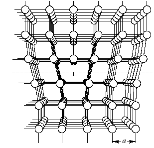
Fig.4.10. Edge dislocation. The linear defect is represented by the edge of an extra half-plane of atoms.
(a) (b)
Fig.4.11 Definition of the Burgers vector, b, relative to an edge dislocation.
In the perfect crystal, an m x n atomic step loop closes at the starting point. In the region of a dislocation, the same loop does not close, and the closure vector (b) represents the magnitude of the structural defect. For the edge dislocation, the Burgers vector is perpendicular to the dislocation line.
Remember N1:
For the edge dislocation, the Burgers vector is perpendicular to the dislocation line. Fig. 4.12 shows a fundamentally different type of linear defect, the screw
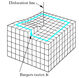
Fig.4.12. Screw dislocation. The spiral stacking of crystal planes leads to the Burgers vector being parallel to the dislocation line.
dislocation, which derives its name from the spiral stacking of crystal planes around the dislocation line.
Remember N2:
For the screw dislocation, the Burgers vector is parallel to the dislocation line.
Remember N3:
The edge and screw dislocations can be considered the pure extremes of the linear defect structure.
Remember N4:
Most linear defects in actual materials will be mixed. Mixed dislocations has both edge and screw character. The Burgers vector for the mixed dislocation is neither perpendicular nor parallel to the dislocation line but retains a fixed orientation in space consistent with the previous definitions for the pure edge and pure screw regions.
The local atomic structure around a mixed dislocation is difficult to visualize, but the Burgers vector provides a convenient and simple description. In compound structures, even the basic Burgers vector designation can be relatively complicated. Fig. 4.13 shows the Burgers vector for Al2O3 structure.

Fig. 4.13 Burgers vector for Al2O3 structure. The large repeat distance in this relatively complex structure causes the burgers vector to be broken up into two (for O2-) or four
( for Al3+) partial dislocations, each representing a smaller slip step. This complexity is associated with the brittleness of ceramics compared to metals.
The large repeat distance in this relatively complex structure causes the Burgers vector to be broken up into 2 (for O2-) or 4 (Al3+) partial dislocations, each representing a smaller slip step. This complexity is associated with the brittleness of ceramics compared to metals.