

Sharp R.The poor man's guide to computer networks and their applications.2004
.pdfThe Poor Man's Guide to Computer Networks and their Applications
Robin Sharp
Informatics and Mathematical Modelling, DTU
April 2004
Contents
1 |
Introduction |
2 |
|
2 |
Networks |
3 |
|
3 |
Layered Architectures |
4 |
|
|
3.1 |
The OSI Reference Model . . . . . . . . . . . . . . . . . . . . . . . . . . . . . . . . |
4 |
|
3.2 |
Other layered architectures . . . . . . . . . . . . . . . . . . . . . . . . . . . . . . . |
8 |
4 |
Services and Protocols |
10 |
|
|
4.1 |
Services . . . . . . . . . . . . . . . . . . . . . . . . . . . . . . . . . . . . . . . . . . |
10 |
4.2Quality of Service . . . . . . . . . . . . . . . . . . . . . . . . . . . . . . . . . . . . . 15
|
4.3 |
Protocols . . . . . . . . . . . . . . . . . . . . . . . . . . . . . . . . . . . . . . . . . |
16 |
5 |
Network Technology |
21 |
|
|
5.1 |
Routers . . . . . . . . . . . . . . . . . . . . . . . . . . . . . . . . . . . . . . . . . . |
22 |
|
5.2 |
Bridges . . . . . . . . . . . . . . . . . . . . . . . . . . . . . . . . . . . . . . . . . . |
23 |
|
5.3 |
LAN Technologies . . . . . . . . . . . . . . . . . . . . . . . . . . . . . . . . . . . . |
24 |
6 |
Basic Protocols in the Internet |
29 |
|
6.1Internet Protocol, IP . . . . . . . . . . . . . . . . . . . . . . . . . . . . . . . . . . . 31
6.2Transmission Control Protocol, TCP . . . . . . . . . . . . . . . . . . . . . . . . . . 36
6.3User Datagram Protocol, UDP . . . . . . . . . . . . . . . . . . . . . . . . . . . . . 39
6.4Internet Application Layer Protocols . . . . . . . . . . . . . . . . . . . . . . . . . . 40
7 Simple Mail Transfer Protocol, SMTP |
40 |
7.1The Basic SMTP protocol . . . . . . . . . . . . . . . . . . . . . . . . . . . . . . . . 41
7.2MIME . . . . . . . . . . . . . . . . . . . . . . . . . . . . . . . . . . . . . . . . . . . 44
1
2 |
|
|
1 INTRODUCTION |
|
8 |
HTTP and the World Wide Web |
|
49 |
|
|
8.1 |
Uniform Resource Identi ers . . . . . |
. . . . . . . . . . . . . . . . . . . . . . . . . |
49 |
|
8.2 |
Hypertext Transfer Protocols . . . . . |
. . . . . . . . . . . . . . . . . . . . . . . . . |
52 |
9 |
Network Programming with Sockets |
|
56 |
|
9.1Java Client Sockets . . . . . . . . . . . . . . . . . . . . . . . . . . . . . . . . . . . . 58
9.2Java Server Sockets . . . . . . . . . . . . . . . . . . . . . . . . . . . . . . . . . . . . 63
10 Remote Procedures and Objects |
64 |
|
10.1 |
Remote Procedure Call . . . . . . . . . . . . . . . . . . . . . . . . . . . . . . . . . |
64 |
10.2 |
Binding . . . . . . . . . . . . . . . . . . . . . . . . . . . . . . . . . . . . . . . . . . |
67 |
10.3 |
Remote Object Invocation . . . . . . . . . . . . . . . . . . . . . . . . . . . . . . . . |
67 |
11 CORBA |
75 |
|
11.1 |
The Object Request Broker . . . . . . . . . . . . . . . . . . . . . . . . . . . . . . . |
76 |
11.2 |
CORBA Interfaces and the CORBA IDL . . . . . . . . . . . . . . . . . . . . . . . |
78 |
11.3 |
CORBA Clients and Servers . . . . . . . . . . . . . . . . . . . . . . . . . . . . . . . |
79 |
12 |
Web Services and SOAP |
85 |
|
|
12.1 |
XML Encoding of the Request Message . . . . . . . . . . . . . . . . . . . . . . . . |
88 |
|
12.2 |
SOAP Response Messages . . . . . . . . . . . . . . . . . . . . . . . . . . . . . . . . |
88 |
|
12.3 |
SOAP Types . . . . . . . . . . . . . . . . . . . . . . . . . . . . . . . . . . . . . . . |
89 |
|
12.4 |
Web Service Clients and Servers . . . . . . . . . . . . . . . . . . . . . . . . . . . . |
92 |
13 |
Further Reading |
97 |
|
1Introduction
These days, computers very rarely operate on their own. Instead, they are connected together by computer networks which enable them to exchange information. There can be many reasons for wanting to do this in relation to a particular computer application. For example:
The application may directly involve transfer of information between human users, as in systems for transferring e-mail or other documents, or in teleconferencing.
The application may involve a need to access an information base of some kind, as in searching the World Wide Web, electronic banking or database applications.
The application may need several computers to collaborate on performing a large calculation, or to share data or other resources, as in many technical computations in engineering, the natural sciences and economic modelling.
The aim of these notes is to present the main concepts of computer networks, give a very short introduction to their architecture and technology and give some simple examples
3
of how the use of networks can be incorporated into applications. There are many books which deal with the subject in much more detail. You should consult some of the references in the bibliography if you want to know more about a particular topic.
2Networks
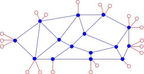
Basically speaking, a computer network consists of a set of nodes connected by communication links. In simple cases, the nodes are end systems, i.e. computers which run applications, using the links to communicate with one another. In larger or more complex systems, however, some of the nodes just deal with aspects of the communication process, such as choosing a suitable route for data which is being sent between two end systems, and do not directly take part in applications. Such nodes are often known as communication nodes. An example of such a network is illustrated in Figure 2.1. The communication nodes are indicated by full circles and the end systems by un lled circles.
Figure 2.1: A network with communication nodes ( ) and end systems ( )
Computer networks are often classi ed according to their physical size, as this to some extent determines the communication technology on which they can be based. It is traditional to distinguish between:
Local Area Networks (LAN): Small networks, with a size of up to a few kilometers, typically covering a building or a single company or institution.
Wide Area Networks (WAN): Large networks, covering a large geographical area, such as a whole country, or perhaps even the whole world.
Metropolitan Area Networks (MAN): Networks covering a town or other relatively large area.
4 |
3 LAYERED ARCHITECTURES |
Some of these distinctions are historically based, since for legal reasons it was at one time important whether the network was run by and for a single owner such as a company or university (who were only allowed to set up a LAN covering a limited area), or whether the network's capacity was intended to be sold to subscribers in general (typically a WAN, which could only be run by an privileged telecommunications monopoly). Nowadays, where telecommunication services have in most countries been extensively liberalised, this type of criterion is less important. However, the basic di erences in technology remain. We discuss some of these below in Section 5.
3Layered Architectures
The requirement that some nodes in a computer network should be able to do more than others leads naturally to the idea that systems in a network can be built up as a number of layers, where the upper layers add some kind of extra functionality to the lower ones. Thus for example, an end system can be built up as a communication node with one or more extra layers to add the functions needed for dealing with the requirements of the applications.
In a layered architecture, each layer { by building on the facilities o ered by the layer beneath { becomes able to o er the layer above a service which is di erent from the service which it itself is o ered. As a rule it will be better (more reliable, more free of errors, better protected against \intruders", . . . ) or will o er more possibilities than the layer beneath. This is achieved by the active components in the N'th layer { often denoted the
(N)-entities { exchanging information with one another according to a set of rules which are characteristic for the layer concerned { the (N)-protocol. A simple example could be that they exchange information with a certain degree of redundancy, so that any errors which are introduced by the layer beneath { the (N-1)-layer { can be detected and corrected. The
(N)-service which they o er to the active components in the (N+1)-layer { the (N+1)- entities { can thus be less disturbed by errors than the (N-1)-service which they are o ered by the (N-1)-layer. This is illustrated in Figure 3.1.
3.1The OSI Reference Model
An important and well-known example of a layered architecture for communication systems is described in the OSI Basic Reference Model [8] developed and standardised by the International Organization for Standardization (ISO) in the 1980s. The acronym OSI stands for Open Systems Interconnection, and is a general term covering everything which has to be considered when systems (especially computer systems) have to cooperate with one another, or { to use a more technical term { to interwork across a communication

3.1 The OSI Reference Model |
|
|
|
|
|
|
|
|
|
|
|
|
|
|
|
|
|
|
|
|
|
|
|
|
|
|
|
|
|
5 |
||||||||||||||||
|
|
|
|
|
|
|
|
|
|
System A |
|
|
|
|
|
|
|
|
|
|
|
|
|
|
|
|
|
|
|
|
|
|
|
System B |
|
|
|
|||||||||
(N+1)- |
|
(N+1)- |
|
|
|
|
|
|
|
|
|
|
|
|
|
|
|
|
|
|
|
|
|
|
|
(N+1)- |
|
|
|
|||||||||||||||||
Layer |
|
|
entity |
|
|
|
|
|
|
|
|
|
|
|
|
|
|
|
|
|
|
|
|
|
|
|
|
entity |
|
|
|
|||||||||||||||
|
|
|
|
|
|
|
|
|
|
|
|
|
|
(N)-Layer o ers |
|
|
|
|
6 |
|
6 |
|
|
$ |
||||||||||||||||||||||
|
|
|
|
|
|
|
|
|
|
6 |
6 |
|
|
|
|
|
|
|
|
|
|
|||||||||||||||||||||||||
|
|
|
|
|
|
|
|
|
|
|
|
|
|
|
|
|
|
|
|
|
|
|
|
|
|
|
|
|
|
|
|
|
|
|
|
|
|
|
|
|
|
|
|
|
||
|
|
|
|
|
|
|
|
|
' |
|
|
$ |
(N)-service |
' |
|
|
|
|
|
|||||||||||||||||||||||||||
|
(N)- |
|
|
|
(N)- |
|
|
Exchange controlled |
- |
|
|
|
|
(N)- |
|
|
|
|
|
|
||||||||||||||||||||||||||
|
|
|
|
|
|
|
|
|
|
|
|
|
|
|
|
|||||||||||||||||||||||||||||||
|
Layer |
|
|
entity |
|
|
|
by (N)-protocol |
|
|
|
|
entity |
|
|
|
||||||||||||||||||||||||||||||
|
|
|
|
|
|
|
|
|
|
& |
|
|
% |
|
|
|
|
|
|
|
|
|
|
|
|
|
|
|
|
|
& |
|
|
|
% |
|||||||||||
|
|
|
|
|
|
|
|
|
|
|
|
|
|
|
|
|
|
|
|
|
|
|
|
|
|
|
|
|||||||||||||||||||
|
|
|
|
|
|
|
|
|
|
|
|
|
|
(N)-Layer uses |
|
|
|
|
|
|
|
|
||||||||||||||||||||||||
|
|
|
|
|
|
|
|
|
|
6 |
6 |
|
|
|
|
|
|
|
6 |
|
6 |
|
|
|
||||||||||||||||||||||
|
|
|
|
|
|
|
|
|
|
|
|
|
|
|
|
|
|
|
|
|
|
|
|
|
|
|
|
|
|
|
|
|
|
|
|
|
|
|
|
|
|
|
|
|
|
|
|
|
|
|
|
|
|
|
|
|
|
|
|
|
|
|
|
|
|
(N-1)-service |
|
|
|
|
|
|
|
|
|
|
|
|
|||||||||||||||
(N-1)- |
|
|
|
|
|
|
|
|
|
|
|
|
|
|
|
|
|
|
|
|
|
|
|
|
|
|
|
|
|
|
|
|
|
|
|
|
|
|
||||||||
|
Layer |
|
|
|
|
|
|
|
|
|
|
|
|
|
|
|
|
|
|
|
|
|
|
|
|
|
|
|
|
|
|
|
|
|
|
|
|
|
|
|||||||
|
|
|
|
|
|
|
|
|
|
|
|
|
|
|
|
|
|
|
|
|
|
|
|
|
|
|
|
|
|
|
|
|
|
|
|
|
|
|
|
|
|
|
|
|
|
|
|
|
|
|
|
|
|
|
|
|
|
|
|
|
|
|
|
|
|
|
|
|
|
|
|
|
|
|
|
|
|
|
|
|
|
|
|
|
|
|
|
|
|
|
|
|
|
Figure 3.1: Principles in a layered architecture
network in a manner which is independent of manufacturers' system-speci c methods. The OSI Reference Model de nes the most basic principles for this purpose.
To do this, the OSI Reference Model describes a layered architecture, de nes which layers are conceptually to be found in a standard communication system, which services these layers o er and which functions the individual layers are expected to be able to perform in order to o er these services. The model speci cally describes seven layers, whose main functions are shown in Figure 3.2.
The lower three OSI layers are intended to supply communication services for transferring data between systems in the network. The Physical layer o ers facilities for transmitting individual bits (or groups of a few bits), typically in the form of electrical or optical signals, on the physical medium1 between two systems. Since most media and the associated transmitting and receiving electronics are susceptible to being disturbed by electrical noise, this does not in itself provide a reliable method of data transfer. The Data Link layer therefore introduces facilities for sending blocks of data and for checking them for errors by the use of error-detecting or -correcting codes. This provides more reliable communication, but can only transmit data between systems which are directly connected, in the sense of being connected by a bre or cable or having access to a shared medium, such as a broadcast channel or a shared bus. To be able to send data to arbitrary nodes which are not directly connected, extra facilities are needed in order to choose a suitable route
1which you should incidentally note is not part of any of the layers.

6 |
3 LAYERED ARCHITECTURES |
|
|
|
|
|
|
|
|
|
|
|
Direct support to appl. processes. |
|
|
|
|
APPLICATION |
(File and job transfer, e-mail, |
||||||
|
|
|
|
|
|
|
|
|
|
|
|
|
|
|
|
|
|
|
|
|
|
|
distributed transactions,...) |
|
|
|
|
|
|
|
|
|
|
|
Transformation of data to syntactic |
|
|
|
|
|
|
|
|
|
|
|
|
|
|
PRESENTATION |
form acceptable to local processes. |
||||||||
|
|
|
|
|
|
|
|
|
|
|
(Character sets, data structures,...) |
|
|
|
|
|
|
|
|
|
|
|
Organisation and synchronisation |
|
|
|
|
|
|
|
|
|
|
|
|
|
|
|
|
|
SESSION |
of dialogues between cooperating |
|||||
|
|
|
|
|
|
|
|
|
|
|
presentation entities. |
|
|
|
|
|
|
|
|
|
|
|
End-to-end transfer of data between |
|
|
|
|
|
|
|
|
|
|
|
|
|
|
|
|
|
TRANSPORT |
session entities. |
|||||
|
|
|
|
|
|
|
|
|
|
|
(Error, sequence and flow control) |
|
|
|
|
|
|
|
|
|
|
|
Transfer of data between arbitrary |
|
|
|
|
|
NETWORK |
||||||
|
|
|
|
|
systems in arbitrary networks. |
||||||
|
|
|
|
|
|
|
|
|
|
|
(Routing, subnets, flow control) |
|
|
|
|
|
|
|
|
|
|
|
Transfer of data between neighbour |
|
|
|
|
|
|
|
|
|
|
|
|
|
|
|
|
|
DATA LINK |
(or other directly connected) systems. |
|||||
|
|
|
|
|
|
|
|
|
|
|
(Error, sequence and flow control) |
|
|
|
|
|
|
|
|
|
|
|
Transfer of physical data units (bits) |
|
|
|
|
|
|
|
|
|
|
|
|
|
|
|
|
|
PHYSICAL |
between data link entities. |
|||||
|
|
|
|
|
|
|
|
|
|
|
(Signalling on physical medium) |
PHYSICAL MEDIUM
Figure 3.2: The OSI Reference Model: The 7 layers
3.1 The OSI Reference Model |
7 |
End system |
Communication network |
End system |
T |
|
T |
N |
|
N |
D |
|
D |
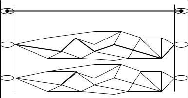
Figure 3.3: Views of a computer network as seen from the Transport, Network and Data Link layers
through a sequence of nodes which are pairwise directly connected. These facilities are provided by the Network layer, which also makes it possible to link together subnetworks which may use completely di erent technologies, as for example a WAN and a LAN.
While the Network layer makes it possible to send data to arbitrary systems in the network, this is not in general enough to provide the type of communication service required by a typical application. Applications are usually built up based on the abstraction that a set of application processes, possibly running in di erent end systems, communicate directly with one another. The Network layer only provides the abstraction that the relevant nodes are connected. To provide the illusion of a channel which directly connects processes running on the nodes, a layer which o ers so-called end-to-end data transfer services is required. This is the function of the Transport layer, which allows us to:
Multiplex several logical communication channels onto a single Network channel between two nodes;
Perform error control on an end-to-end basis on each of the channels separately;
(Possibly) control the ow of data on an end-to-end basis on each of the channels separately.
Hide the details of the network or set of interconnected networks which are being used.
The relationship between the Data Link, Network and Transport layers is illustrated in Figure 3.3.
On the basis of the end-to-end data transfer service o ered by the Transport layer, the upper three layers provide services intended to support a large variety of applications. At the Transport layer level, the `data' being transferred is still regarded as just a collection of bits. The upper layers make sure that these bits provide the application with meaningful
8 |
3 LAYERED ARCHITECTURES |
data in a form which the application can understand. The Session layer is used to organise dialogues between two or more parties involved in an application, the Presentation layer converts data into a representation which the application in the receiving system can understand, and the Application layer o ers functionality such as transfer of les or coordination of parallel activities, which are required in general by applications, or facilities such as mail or Web transfer required by particular applications. We shall look more closely at some examples of particular Application protocols later in these notes. Note that the application itself is { like the physical medium { not covered by the model. The application processes are to be considered as users of the facilities o ered by the Application layer.
The importance of the OSI Reference Model is that it introduced a standard architecture and a standard notation for many concepts related to data communication. The terms given in italics above are examples of terms introduced in the model. That, for example, there are seven layers is relatively unimportant, and the explanations of why there should be exactly seven are mostly entertaining rather than strictly technical. In practice, for descriptive purposes some of the layers (particularly the Data Link, Network and Application layers) are often divided into sub-layers, while implementations, on the other hand, often implement several layers as a single unit.
3.2Other layered architectures
The OSI Reference Model architecture is not the only layered architecture which you may meet in communication systems. Several commercial manufacturers have developed products which are structured in a similar way. Well-known examples are IBM's SNA architecture and Digital's DECNET. Naturally, the protocols used are not in general the same as OSI protocols, and the layers do not always correspond exactly to the OSI ones, especially in the so-called Upper Layers: the OSI Session, Presentation and Application layers.
A particularly common alternative arrangement is to consider the three upper layers as one unit, an `Application-oriented layer' which depends directly on the Transport layer. A well-known example of this approach is found in the so-called Internet protocols, commonly used in Unix-based systems. Here, a whole series of application protocols { for example, for le transfer (FTP), electronic mail (SMTP), handling virtual terminals (TELNET) and information retrieval (HTTP) { run directly over the Transport layer, while the standard OSI layer structure is used for the Network layer and below. This is illustrated in Figure 3.4. Similar arrangements are often found in local area networks, where OSI protocols are used up to the Transport layer, while the architecture and choice of protocols in the Upper Layers deviates from the OSI standards.
Finally, in modern telecommunication systems, a somewhat di erent layered architecture can be found in systems based on ATM (Asynchronous Transfer Mode), a technology for

3.2 Other layered architectures |
9 |
Direct support to appl. processes.
APPLICATION Transformation of data to syntactic form acceptable to local processes.
|
|
|
|
|
End−to−end transfer of data between |
|
|
TRANSPORT |
application entities. |
||
|
|
|
|
|
(Error, sequence and flow control) |
|
|
|
|
|
Transfer of data between arbitrary |
|
|
NETWORK |
|||
|
|
systems in arbitrary networks. |
|||
|
|
|
|
|
(Routing, subnets, flow control) |
|
|
|
|
|
Transfer of data between neighbour |
|
|
|
|
|
|
|
|
DATA LINK |
(or other directly connected) systems. |
||
|
|
|
|
|
(Error, sequence and flow control) |
|
|
|
|
|
Transfer of physical data units (bits) |
|
|
|
|
|
|
|
|
PHYSICAL |
between data link entities. |
||
|
|
|
|
|
(Signalling on physical medium) |
PHYSICAL MEDIUM
Figure 3.4: The layered architecture used in the Internet
10 |
4 SERVICES AND PROTOCOLS |
supporting high-speed transfer of data over a local area or wide area network. This architecture is described by the Broadband ISDN Protocol Reference Model (B-ISDN PRM) [27]. In this model, although the layers roughly correspond to the OSI RM, there are several important technical di erences, especially with respect to the way in which control and signalling information is transferred: In OSI, it forms part of the ordinary data ow; in B-ISDN, it is transferred over a separate connection.
4Services and Protocols
The service o ered by a layer describes the facilities o ered by the layer viewed as a `black box'. In other words the service describes what the layer o ers without telling us how this is achieved. The protocol is the set of rules for how to behave in order to o er the required service. This is analogous to concepts used in program design: the service corresponds to a description of an interface and the protocol to its implementation.
4.1Services
Properties of services fall into two general classes, one concerned with the logical operation of the service (\what does it do?"), and the other with its economy (\what does it cost?"). In these notes, we shall only look at the logical properties of services. Important ones include:
Sequence preservation
Data unit synchronisation
Freedom from error
Connection-orientation
(N)-peer operation
Simplex/duplex/multiplex operation
Expedited data
Security
Let us look at these concepts in turn.
4.1.1Sequence preservation
In a service which o ers sequence preservation, messages sent by a sender are received in the same order as they were sent. This property of a service can be extremely important to some types of service user. For example, in an application in which video frames are to be