

Sharp R.The poor man's guide to computer networks and their applications.2004
.pdf4.1 Services |
11 |
5 |
4 3 |
2 |
1 |
Service |
5 |
4 3 |
2 |
1 |
5 |
4 3 |
2 |
1 |
Service |
Cut anywhere
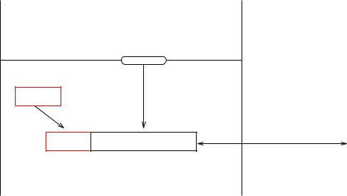
Figure 4.1: A block-oriented service (above) and a stream-oriented service (below).
transferred from one system to another for immediate display, it would be very inconvenient if the frames arrived in a di erent order, as the application would then itself have to manage the task of bu ering and re-ordering them before display. Likewise, changes to a database should not arrive in a di erent order than the one chosen by the user. On the other hand, for an application which transfers numbered disk blocks from one system to another, in order to maintain identical copies of a disk on two systems, sequence preservation is often irrelevant.
4.1.2Data unit synchronisation
In a service which o ers data unit synchronisation, there is a one-to-one correspondence between the messages passed to the service for transmission and the messages delivered to the receivers. In other words, each message supplied by a user for transmission will { if it arrives at all { be delivered to the intended receiver(s) as a unit. Such services are sometimes called message oriented services or block oriented services, as they deliver blocks of data in their entirety.
A common alternative is for the service to be stream oriented. This means that the boundaries between units of data supplied to the service are not necessarily preserved when the data are delivered to the receiver. Data are regarded as making up a (potentially endless) stream, which can be chopped up and delivered in units of any convenient size. This is illustrated in Figure 4.1.
4.1.3Freedom from error
An error-free service delivers the same messages as those which are sent o , without loss or corruption of any kind. In communication systems, the basic types of error are:

12 |
4 SERVICES AND PROTOCOLS |
Message loss: the receiver fails to receive a message which has been sent by the sender. Message corruption: the receiver receives a message which di ers from that sent by the
sender.
Spurious message: the receiver receives a message which has not been sent by the (apparent) sender.
Other types of error, such as duplication or misdelivery of messages, can be expressed as combinations of these basic error types.
A service is often described in terms of its error rate, which roughly speaking is the number of erroneous units of data as a fraction of the number of units of data which the sender tries to send. Common measures of this are:
Bit Error Rate (BER), measured as the number of bits which are in error as a fraction of the total number of bits sent.
Residual Error Rate (RER), measured as the number of erroneous blocks of data as a fraction of the number of blocks sent:
RER = Nl + Nc + Nu
Ns + Nu
where Ns is the number of blocks sent by the sender, Nc the number of corrupted blocks received, Nl the number of lost blocks and Nu the number of spurious blocks received by the receiver (but not sent by the genuine sender).
4.1.4Connection-orientation
In a connection-mode service, the users of the service have to establish a connection with one another before they can exchange `real' data. The connection is a logical channel through which the real data will be sent, and is set up by exchange of particular types of message in a so-called connection establishment phase of communication. This is followed by the data transfer phase of communication, in which actual data are exchanged, andnally by a connection release phase, in which the connection is broken. For a reliable service, connection release will of course be something which the users decide voluntarily to do; an unreliable service can also produce involuntary release of a connection (in OSI jargon known as a Provider Abort). You probably recognise this style of operation from the ordinary telephone service, which is the archetypal example of a connection-oriented service, where you have to set up the connection before you can exchange `data'. In the case of an old-fashioned telephone the data will of course be in the form of digital or analog encoded speech; in more modern systems other possibilities may also be available.
The alternative to this mode of operation is seen in a connectionless-mode service. Here, it is not necessary to set up a connection before exchange of data. Essentially, each message is
4.1 Services |
13 |
then sent independently of the others, and the service has no memory of what has been sent previously to the same destination. The obvious analogy here is to the postal service: when you send a letter, you do not need to set up an agreement with the intended receiver before you post the letter. Obviously, this mode of operation requires less administration, in the form of connection establishment. The downside is that, since you have no guaranteed logical channel through to the intended receiver, there is no way of guaranteeing that messages will arrive in the same order as they were sent { or even that they will arrive at all. A common nickname for this style of service is send-and-pray ! Moreover, much of the information transmitted during connection establishment, such as the address of the intended receiver and other properties to be supplied by the service, will have to be repeated for each message when a connectionless-mode service is used.
4.1.5Multi-peer operation
In a service which o ers point-to-point operation, only two users are involved, and they can communicate with one another. In the simplest case, the two parties have equal status, and we speak of a two-peer or peer-to-peer service. Later in these notes, we shall see that there are other important forms of two-party communication, for example in client-server systems, where the parties have di erent status.
In a service which o ers multi-peer operation, several users can communicate with one another during an instance of communication. Multi-peer services fall into various classes, depending on the pattern of communication which can be achieved:
Broadcast: All available users of the service receive a message sent by one of them. Multicast: The sender can select a particular subset of users (often known as a multicast
group) who are intended to receive a particular message or messages.
Inverse broadcast: A single receiver can receive simultaneously from all the other service users.
4.1.6Simplex/duplex/multiplex operation
A service which o ers simplex operation is able to transfer messages in one direction only through a logical or physical channel. In duplex operation, messages can pass in both directions. If they can pass in both directions at once, we speak of full duplex operation; if in one direction at a time, half duplex operation.
A multiplex service o ers access to many users at once by providing some mechanism for sharing the service between them. A duplex service is a special case of this, where there are only two users who share the service, sending in di erent directions.
14 |
4 SERVICES AND PROTOCOLS |
4.1.7Expedited data
Expedited data is an OSI term for data to be transferred with high priority. By de nition, expedited data will arrive not later than `ordinary' data sent subsequently to the same destination, and may arrive before ordinary data sent to the same destination at an earlier instant of time. Note that this is not a guarantee that they will arrive before ordinary data sent at the same time! In Internet protocols, the term urgent data is used for essentially the same concept.
To model this, we can model the service as containing a prioritised queue for the messages in transit, so that queue elements sent via the expedited data service can overtake those sent via the normal service. Obviously, this is in con ict with the concept of sequence preservation for messages sent between two service users, seen from a universal point of view. But the individual services (normal and expedited) may each possess the sequence preservation property when considered separately.
Although the OSI term is con ned to a single high-priority service, the concept can be generalised to cover arbitrary numbers of priority levels. This type of service is commonly o ered at the hardware level in Local Area Networks. Examples are the ISO/IEEE Token Bus [11], which o ers four levels of priority, and the ISO/IEEE Token Ring [12], which o ers eight levels.
4.1.8Security
A secure service is one which prevents unauthorised persons from obtaining access to data transferred by it. This means that data cannot be read or altered by parties other than the intended sender and receiver(s). This is a matter of extreme practical importance, and a great deal of e ort has been expended on developing methods to protect data in transit from `intruders'.
Various types of security can be identi ed. A generally accepted classi cation is:
Con dentiality: A con dential service provides protection of data from unauthorised disclosure. This protection may, for example, cover:
1.All data sent between users of the service,
2.Particular elds within data (for example, elds containing passwords or keys),
3.Information about the amount of data tra c being transmitted.
The primary mechanism for ensuring con dentiality of data is encipherment, and a study of cryptography is essential for understanding the issues involved.
Integrity: A service o ering (data) integrity takes measures to withstand active attempts to modify data being passed via the service. As with con dentiality, all data may be protected, or only selected elds.

4.2 Quality of Service |
15 |
Availability: A service which ensures availability is designed to make the service available to (authorised) users at all times. It is not possible for intruders to prevent access by attacking the systems which provide the service. As you may know, typical attacks may come in the form of vira, worms, trojan horses or by the service being ooded with excessive numbers of messages (so-called denial of service (DoS) attacks).
Authentication: An authenticated service o ers its users facilities for con rming that the party which they are communicating with actually is the party that they believe they are communicating with. You should be aware that this is not trivial in a network, since you cannot really `see' who you are talking to, and have to rely on more indirect methods of identi cation, which might be faked. Just imagine the analogous situation in the telephone network, illustrated in Figure 4.2: How can the man in the picture tell whether the person on the other end of the phone line really is Mary Smith from the Town Hall, if he has never met or talked to Mary Smith before?
Non-repudiation: A service with non-repudiation o ers undeniable proof that data have been sent or received by a particular service user. Non-repudiation with proof of origin prevents the sender from falsely denying that it has sent data; non-repudiation with proof of delivery prevents the receiver from falsely denying that it has received data.
The rst three of these (Con dentiality, Integrity, Availability) are the most basic security properties, and are often (jokingly?) known as the CIA properties.
4.2Quality of Service
The quantitative properties of a service are commonly summarised in terms of a set of parameters collectively known as Quality of Service (QoS) parameters. These describe features of the service such as its:
Throughput: The number of bits of data which can be transferred per unit time.
Delay: The time required to:
1.Establish a connection
2.Transfer a data block between sender and receiver
3.Release a connection
Reliability: The probability of failure in:
1.Establishing a connection
2.Transferring a data block between sender and receiver
3.Releasing a connection
Resilience: The probability of unrequested disconnection.
This is Mary Smith from the Town Hall here
Figure 4.2: An authentication problem
16 |
4 SERVICES AND PROTOCOLS |
Error rate: The BER and/or RER (as de ned above).
Protection: Degree of protection against intruders who attempt:
1.Passive monitoring of information in transit.
2.Active modi cation, replay, addition or deletion of information in transit.
Priority: This can be understood in two senses:
1.Priority in delivery of data. High priority data is delivered \faster".
2.Priority in maintaining the requested QoS if the service provider has to degrade the service for some users. A high priority service in this sense is more likely to get what was requested.
QoS parameters are often speci ed in terms of a target (mean or median) value, together with some indication of the acceptable spread of values, given for example in terms of permissible maximum and minimum values or in terms of a variance. It may also be relevant to specify a (prioritised) list of acceptable discrete values. For example, you might want to state that a service o ers (or is requested to o er):
Throughput: Preferably 128 kbit/s, but otherwise 56 kbit/s.
Delay in data transfer: 200 ms., +5 ms./-10 ms.
Resilience: 1 10 8
BER: 1 10 9.
Priority in delivery: Highest.
The importance of the various parameters depends strongly on the type of data being transferred by the service. For example, the variation in data transfer delay (often known as the jitter) is relatively unimportant for transfer of data such as text les, whereas it is a very important parameter for transfer of continuous media, such as live video or audio in a multimedia application, where variations in the delay can markedly reduce the quality of the user's experience.
4.3Protocols
A communication protocol is a set of rules which describe how a set of parties are to behave in order to achieve successful communication, which in a layered architecture means that they provide the service which the layer is supposed to provide. Typically the rules specify:
Which messages are to be exchanged in response to particular events which occur either at the interface to the layer or internally (say in the form of timeouts). Such rules are known as the rules of procedure for the protocol.
The format and encoding of the messages for transfer between the participating entities.
4.3 Protocols |
17 |
(N)−SDU |
(N+1)−Layer |
|
|
|
|
|
|
|
|
(N)−SAP |
|
|
|
|
(N)−PCI |
|
(N)−Layer |
|
|
|
|
(N)−SDU |
Transmission |
(N)−PCI |
|
|
|
(N)−PDU |
via (N)−Protocol |
|
|
Figure 4.3: Embedding of a data unit supplied by the user into a PDU
In OSI terminology, the messages exchanged as part of the protocol are known as Protocol Data Units, or more commonly just as PDUs. An initial letter is often used to indicate which layer the protocol belongs to: APDU for Application, TPDU for Transport, NPDU for Network, DPDU for Data Link and so on, or more generally (N)-PDU for a PDU in layer N of a layered architecture. A particular protocol may use several types of PDU; these are usually given descriptive names (Data PDU, ACK PDU, etc.). If you read about non-OSI protocols, you may also nd a number of other, rather less precise, terms in use: packets, frames, blocks and so on, somewhat arbitrarily chosen for the individual protocols.
4.3.1Protocol Control Information
In layer N of a layered architecture, any type of data to be sent between the users of the layer (in layer N + 1) must be packed into an (N)-PDU, typically a Data PDU. This will contain the data supplied by the user, together with information known as Protocol Control Information (or just PCI), which is needed to control the exchange of PDUs according to the rules of the protocol. For example:
Information identifying the source and destination of the PDU.
Sequence numbers, used to detect missing or misordered PDUs.
Checksums, used to detect corruption of PDUs.
Timestamps, used to detect stale information.
This is illustrated in Figure 4.3.

18 |
4 SERVICES AND PROTOCOLS |
The gure illustrates a simple case, where the amount of data supplied (in the gure denoted the Service Data Unit or SDU, in accordance with OSI notation) can convenientlyt into a single PDU, and where all the PCI is added as a header at the start of the PDU. In more complex cases, some of the PCI may appear in a trailer at the end of the PDU2, or it may be necessary to:
Divide the data in the SDU up among several PDUs. This is usually known as segmentation or fragmentation. The opposite process, known as reassembly takes place in the receiver, in order to recover the entire SDU with all its parts in the correct order.
Include several SDUs in a single PDU. This process, known as packing, may be convenient for e ciency reasons. The receiver will then have the task of unpacking the SDUs for delivery to the users.
Some types of PDU, used for purely administrative purposes such as acknowledging receipt of a PDU, do not need to contain data supplied by the service user, and thus consist solely of PCI.
4.3.2PCI in a layered architecture
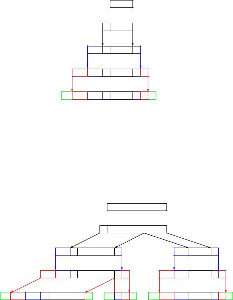
Since PCI has to be added in each layer of a layered architecture, in order to suit the rules of the various protocols in use, it should be clear that the actual data being exchanged by an application can be embedded in a large amount of headers and trailers originating in the various layers. A simple example of this is illustrated in Figure 4.4, where we imagine an Internet-style layered architecture with an Application layer supported directly by the Transport layer. In a full OSI architecture, two more layers of PCI, from the Session and Presentation layers, have to be added. The actual application data are rst embedded in an APDU to be exchanged using the chosen Application layer protocol. This APDU becomes data to be sent in a TPDU to be exchanged using the chosen Transport layer protocol, and so on.
Figure 4.4 shows the simplest case, in which each (N)-PDU ts into the payload of a single (N-1)-PDU. In many practical cases, this may not be possible, as the rules of the protocol may prescribe a maximum length for the PDUs which can be sent. If the (N)- PDU cannot be embedded into a single (N-1)-PDU, then it must be segmented into several (N-1)-PDUs. An example of what might happen is shown in Figure 4.5. Here the APDU is divided among two TPDUs, each of which gives rise to a single NPDU, of which the rst has to be segmented and sent as two DPDUs, while the remaining one ts into a single DPDU.
2this is often convenient for checksums as the entire PDU usually has to be processed in order to evaluate the checksum.
4.3 Protocols |
19 |
Layer |
|
User |
Application data |
A |
APDU |
T |
TPDU |
N |
NPDU |
D |
DPDU |
Figure 4.4: Embedding of application data in PDUs in a layered architecture
Layer
User
A |
|
|
H) |
|
|
J) |
|
|
H)I) |
|
J)K) |
||
|
|
I |
|
|
K |
|
T |
|
|
|
|
|
|
N |
|
m) |
|
M) |
|
|
|
m)n) |
M)N) |
|
|
||
|
n |
|
N |
|
|
|
D
Application data
APDU
TPDU
NPDU
DPDU
Figure 4.5: Embedding of application data in PDUs in a layered architecture where segmentation is necessary

20 |
|
|
|
|
|
|
|
|
|
|
|
|
|
|
|
|
|
|
|
|
|
|
|
|
4 SERVICES AND PROTOCOLS |
||||||||||||||||||||
|
|
|
|
|
|
|
|
|
|
|
|
|
|
|
|
|
|
|
|
|
|
|
|
|
|
|
|
|
|
|
|
|
|
|
|
|
|
|
|
|
|
|
|
|
|
(a) |
DATA PDU |
t |
|
|
s |
|
|
d |
l |
|
|
|
|
|
|
|
|
|
b |
|
|
c |
|
||||||||||||||||||||||
|
|
|
|
|
|
|
|
|
|
|
|
|
|
|
|
|
|
|
|
|
|
|
|
|
|
|
|
|
|
|
|
|
|
|
|
|
|
|
|
|
|
|
|
|
|
(b) |
ACK PDU |
t |
|
|
s |
|
|
d |
|
|
|
c |
|
|
|
|
|
|
|
|
|
|
|
|
|
|
|
|
|
|
|
|
|
||||||||||||
Figure 4.6: Example formats for two PDU types
The PDU types and eld names refer to the example in the main text.
A commonly observed practical consequence of this is that the e ective data rate available for transfer of application data may drop suddenly when the application data reach a certain critical size. Whether (and when) this happens depends on the maximum PDU sizes dictated by the individual protocols in use in the protocol suite.
4.3.3A simple data transfer protocol
As an example, suppose we wish layer N to provide a connectionless, block oriented data transfer service for its users (in layer N + 1). A very simple data transfer protocol in layer N for this purpose might specify:
1. Rules of procedure:
If a user in layer N + 1 requests transfer of a block of data b to a destination d, this block will be embedded in a DATA PDU and transmitted to d via the service provided by layer N 1.
If a DATA PDU with a correct checksum is received from source s, an acknowledgment formatted as an ACK PDU will be sent back to s via the service provided by layer N 1.
If a DATA PDU with an incorrect checksum is received from source s, it will be ignored, i.e. no action will be taken and no acknowledgment sent.
If no acknowledgment is received by the sender within a time T after the transmission of a DATA PDU, the sender will retransmit the PDU via the service provided by layer N 1.
2.PDU formats:
A DATA PDU containing data b to be sent from source s to destination d will be formatted as shown in Figure 4.6(a), where t is the 8-bit sequence 10000001, s and d are represented by 32-bit IP addresses, l gives the number of octets3 of data in b expressed as a 16-bit unsigned binary number, and c is a 32-bit checksum eld evaluated over all the other elds of the PDU according to the CRC-32 algorithm.
38-bit units