

Sharp R.The poor man's guide to computer networks and their applications.2004
.pdf6.1 Internet Protocol, IP |
31 |
described in the previous section would be used in these layers. If communication is also to extend over a public WAN, an ITU-T protocol suite such as ATM would typically be used; in practice, the choice of protocol in a WAN will be made by the Internet Service Provider (ISP) who o ers the IP service, and the user is unaware of what is going on in the layers below the Network layer.
6.1Internet Protocol, IP
IP is the basic Network layer protocol used in the Internet. The full name of the protocol may cause you some confusion, since the word \internet" has two meanings: When spelt with a small \i" it refers to a type of protocol which is used to o er Network layer services over a set of interconnected subnets, possibly based on di erent technologies, while with a large \I" it refers to the whole concept of the modern Internet. A more correct name for IP would really be \the Internet internet protocol", but by now it is too late to change!
IP is a connectionless-mode protocol which is used to implement a connectionless-mode, full duplex, point-to-point or multicast stream service for data transfer. IP o ers facilities for segmentation and reassembly, and for various forms of routing. It is de ned in two versions:
1.\Classic" IP, often known as IPv4, which identi es the source and destination systems by 32-bit addresses. This is described in the Internet document RFC791 which forms part of Internet Standard 5 [16].
2.Internet Protocol version 6, often just known as IPv6, which identi es source and destination by 128-bit addresses and includes more comprehensive facilities for dealing with di erent classes of tra c, incorporating security, and other features. The protocol is described in RFC1883 [26], and the addressing scheme in RFC2373 [24].
Most current ISPs support IPv4, but a considerable international e ort is currently going into the deployment of IPv6. An important reason for this is that the number of systems attached to the Internet is increasing so rapidly that the supply of 32-bit addresses used in IPv4 is running out.
The format of an IPv4 PDU is shown in Figure 6.2. The header consists of all the elds from the version number up to and including the padding, while the rest of the PDU contains the payload data, normally a PDU (or part of a PDU) from some higher level protocol such as TCP or UDP. The Protocol eld contains information about which higher level protocol it is: for example, the value 6 indicates TCP and 17 UDP. The length of the header (in units of 32-bit words) is given by the Header Length eld, while the Total Length eld gives the length of the entire PDU in octets (8-bit units). The Type of Serviceeld contains information which in principle speci es the quality of service to be o ered to the PDU, although very few IPv4 routers actually handle this eld in practice. The

32 |
6 BASIC PROTOCOLS IN THE INTERNET |
Bit |
|
|
|
|
|
|
|
|
|
|
|
|
|
|
|
|
|
|
|
|
|
|
|
|
|
|
|
|||
0 |
|
|
|
|
15 |
|
|
|
|
31 |
||||||||||||||||||||
|
|
|
|
Header |
|
|
|
|
|
|
|
|
|
|
|
|
|
|
|
|
|
|
|
|
|
|
|
|
|
|
Version |
Type of service |
|
|
|
|
|
|
Total length |
|
|||||||||||||||||||||
length |
|
|
|
|||||||||||||||||||||||||||
|
|
|
|
Identification |
|
Fragment info. |
|
|||||||||||||||||||||||
|
|
|
|
|
|
|
|
|||||||||||||||||||||||
|
Time−to−live |
|
|
Protocol |
|
|
|
|
|
Header checksum |
|
|||||||||||||||||||
|
|
|
|
|
|
|
|
|
|
|
|
|
|
|
|
|
|
|
|
|
|
|
|
|||||||
|
|
|
|
|
|
|
|
|
Source address |
|
|
|
|
|
|
|
|
|
|
|
|
|
||||||||
|
|
|
|
|
|
|
|
|
|
|
|
|
|
|
|
|
|
|
|
|
|
|
||||||||
|
|
|
|
|
|
|
|
Destination address |
|
|
|
|
|
|
|
|
|
|
|
|
|
|||||||||
|
|
|
|
|
|
|
|
|
|
|
|
|
|
|
|
|
|
|
|
|
|
|
|
|||||||
|
|
|
|
|
|
|
|
|
|
|
|
|
|
|
|
|
|
|
|
|
|
|
|
|||||||
|
|
|
|
|
|
|
|
|
Header options |
|
|
|
|
|
|
|
|
|
|
|
|
|
||||||||
|
|
|
|
|
|
|
|
|
|
|
|
|
|
|
|
|
|
|
|
|
|
|
|
|
|
|||||
|
|
|
|
|
|
|
|
|
|
|
|
|
|
|
|
|
|
|
|
|
|
|
|
Padding |
|
|||||
|
|
|
|
|
|
|
|
|
|
|
|
|
|
|
|
|
|
|
|
|
|
|
|
|||||||
|
|
|
|
|
|
|
|
|
Data (payload) |
|
|
|
|
|
|
|
|
|
|
|
|
|
||||||||
|
|
|
|
|
|
|
|
|
|
|
|
|
|
|
|
|
|
|
|
|
|
|
|
|
|
|
|
|
|
|
|
|
|
|
|
|
|
|
|
|
|
|
|
|
|
|
|
|
|
|
|
|
|
|
|
|
|
|
|
|
|
|
|
|
|
|
|
|
|
|
|
|
|
|
|
|
|
|
|
|
|
|
|
|
|
|
|
|
|
|
|
|
Figure 6.2: Format of an IP version 4 PDU

6.1 Internet Protocol, IP |
33 |
Fragment Information eld contains two 1-bit ags which indicate whether segmentation (in IP known as \fragmentation") may take place and whether this PDU contains the last fragment or not, followed by a 13-bit subeld giving the position of the fragment in the unfragmented original, measured in units of 8 octets, where the rst fragment starts at octet 0. The Time-to-Live eld is used to ensure that the PDU will be thrown away if it does not reach its destination within a certain period of time. It is initialised to the maximum acceptable lifetime for the PDU (in seconds), and decreased by at least one second in every network node through which the PDU passes; if the PDU spends more than one second in the node, the eld is decreased by the time actually spent. If the eld reaches zero, the PDU is discarded. This ensures that undeliverable PDUs do not continue to wander round in the network, wasting its resources. Finally, the PDU may contain a number of Option elds, which specify information about which route is to be taken to the destination, record information about the actual route, specify security parameters or carry timestamps. The Padding eld contains a number of 0-bits which ensure that the options (and therefore the header as a whole) ll an integral number of 32-bit words. For full details, you should look at RFC791 [16].
6.1.1IP Addresses
An IP address designates a system in a network which operates according to Internet conventions6 . IP addresses can be allocated to a system statically by a system manager when the system is set up, or dynamically from a pool of available addresses when the system is booted. The dynamic method requires you to have access to a server which can supply your system with a currently free IP address. To contact this server, the operating system uses the Dynamic Host Con guration Protocol (DHCP) [23], and the server is therefore usually called a DHCP server.
IPv4 addresses are traditionally written as a sequence of four decimal numbers separated by dots, for example 130.225.76.44, where each number lies in the range [0::255] and is the decimal value corresponding to 8 bits of the address. IPv6 addresses are correspondingly written as a sequence of 8 hexadecimal numbers separated by colons, where each number corresponds to 16 bits of the address. Both IPv4 and IPv6 addresses are structured, with the leading bits of the address denoting the network or subnetwork in which the node is placed, and the trailing bits denoting the particular system (well: interface) within this network. How many bits are used for each purpose depends on the so-called class of the network, where the class re ects some (historical) idea about how many end systems the network is likely to host. The scheme for IPv4 addresses is shown in Figure 6.3. A subset of the IP addresses in each class are allocated for use in systems which will not be connected
6Strictly speaking the address designates not the node or system itself, but a network interface in the node, which in practice means that it is associated with a network adapter card. So if your system uses several network cards at the same time, it will normally use several IP addresses.
34 |
6 BASIC PROTOCOLS IN THE INTERNET |
Address |
|
|
IPv4 address classes |
|
|
class |
|
|
|
|
|
A |
0 |
|
|
|
|
n n n n n n n |
h h h h h h h h |
h h h h h h h h |
h h h h h h h h |
||
|
|
1−127 |
0−255 |
0−255 |
0−255 |
B 1 0  n n n n n n n n n n n n n n
  h h h h h h h h h h h h h h h h
128−191 0−255 0−255 0−255
C 1 1 0 n n n n n n n n n n n n n n n n n n n n n
  h h h h h h h h
|
|
192−223 |
0−255 |
|
0−255 |
0−255 |
|||
|
|
|
|
Network id |
Host id |
||||
Multi− |
|
|
|
|
|
|
|
|
|
1 1 1 0 |
|
|
|
|
|
|
|
||
cast |
|
|
|
|
|
|
|
|
|
|
224−239 |
0−255 |
|
0−255 |
0−255 |
||||
|
|
|
|||||||
|
|
|
|
|
|
Multicast group id |
|
|
|
|
|
|
|
|
|
|
|
||
|
|
|
|
|
|
|
|
||
|
|
|
|
Private Network addresses |
|
||||
A |
0 |
|
|
|
|||||
0 0 0 1 0 1 0 |
h h h h h h h h |
h h h h h h h h |
h h h h h h h h |
||||||
|
10 |
0−255 |
|
0−255 |
0−255 |
||||
B |
1 0 |
1 0 1 1 0 0 |
0 0 0 1 n n n n |
h h h h h h h h |
h h h h h h h h |
|
|
|
172 |
16−31 |
0−255 |
0−255 |
|
C |
|
|
|
|
|
|
1 1 0 |
0 0 0 0 0 |
1 0 1 0 1 0 0 0 |
n n n n n n n n |
h h h h h h h h |
||
|
|
|
192 |
168 |
0−255 |
0−255 |
Figure 6.3: IPv4 addresses (above) and Private Network addresses (below)
6.1 Internet Protocol, IP |
35 |
to the Internet. These are known as Private Network (PN) addresses, and are of course not globally unique: There can be many systems with the address, say, 192.168.25.1 in the world!
The number of bits which identify the network (or indicate that the address is the address of a multicast group) is often specifed by a so-called netmask, which is the pattern of bits which can be used to remove the host id or multicast group id part of the address. This is summarised in Table 6.1. When you connect a system to the Internet, you usually need to
Address |
Length of |
Netmask |
Class |
Network id |
|
A |
8 |
255.0.0.0 |
B |
16 |
255.255.0.0 |
C |
24 |
255.255.255.0 |
Multicast |
4 |
240.0.0.0 |
|
|
|
Table 6.1: IPv4 address structure and netmasks
supply a value for the netmask to be used in your part of the network.
6.1.2Internet Names
Finally, you may be wondering how the IP addresses are related to the Internet host names which turn up in mail addresses, Web addresses and so on. For example:
www.rfc-editor.org hobbits.middle_earth.net esmeralda.imm.dtu.dk stop.it
Like an IP address, a name identi es a system (interface), but it has no xed length and its structure re ects the administrative domains which are responsible for allocating the name. The elements of the name are given in order of increasing signi cance, separated by dots. For example, www.rfc-editor.org refers to the the system www within the sub-domain rfc-editor within the top level domain org.
The top level domain is usually a two-letter code referring to a particular country (dk, it, uk, ru,. . . ) or to a general class of names (org, net, mil, com,. . . ), each of which has its own naming authority responsible for allocating names. For example, names in the top level domain dk are registered by the Danish naming authority, those in ru by the Russian authority, and so on, while names in org (which belong to non-pro t organisations)
36 |
6 BASIC PROTOCOLS IN THE INTERNET |
are registered by the Public Interest Registry in Virginia, USA, those in net and com by Verisign Global Registry Services and so on. A full list of the rules has been published by the Internet Assigned Numbers Authority (IANA), which administers names and addresses in the Internet, and can be found on the Web at:
http://www.iana.org/domain-names.htm
Note that, unlike (global) IP addresses, which refer to a physical network in a particular physical location, Internet names do not necessarily tell you anything about where in the world the system is located, just as your personal name does not tell anything about where you are located either, whereas your address does! This is the essential di erence between a name and an address. The Internet name just tells you about where the name has been registered.
In many cases, for practical reasons, the top-level registration authority in fact delegates the ability to register names to the sub-domains under its control. So for example, with a name such as esmeralda.imm.dtu.dk, the sub-domain name dtu would be registered directly with the dk authority, the sub-sub-domain name imm would be alllocated by and registered with an authority for dtu.dk, and the host name esmeralda would be allocated by and registered with an authority for imm.dtu.dk.
The mapping between names and the corresponding addresses is maintained via the Domain Name Service (DNS), a large distributed database from which information can be retrieved by using the DNS Application layer protocol. This is a client-server protocol, and when you attach a system to the Internet, you usually need to supply the IP address of the DNS server which your system (as client) will ask rst, when it needs to nd the IP address corresponding to a given name. If this server does not know the answer, it will pass the query on to other DNS servers, and so on.
6.2Transmission Control Protocol, TCP
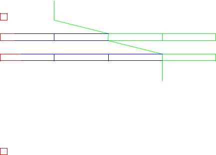
TCP is one of several Transport layer protocols in common use in the Internet, and is described in Internet RFC793, also known as Internet Standard 7 [17]. TCP is a connectionmode protocol which is used to implement a connection-mode, full duplex, point-to-point stream service for data transfer, based on a connectionless-mode Network service, as provided by IP. For tra c between a source identi ed by IP address IP s and a destination identi ed by IP d, TCP makes it possible to set up a large number of connections distinguished by so-called port numbers. This provides a form of multiplexing, as illustrated in Figure 6.4. Port numbers are integers in the range [0; 65535]. Many of the smaller port numbers (up to 1023) are o cially assigned for use by standard Internet application servers. Attempts to make a connection to assigned ports should only be made in order to
6.2 Transmission Control Protocol, TCP |
37 |
Ports
|
|
7496 |
|
|
|
123 |
to |
|
|
25 |
Assigned |
|
|
110 |
|
|
|
80 |
|
IPs |
IPd |
|
|
NTP POP3
HTTP SMTP
Figure 6.4: TCP ports used for multiplexing tra c between two IP addresses
run the appropriate application protocol. Ports from 1024 up to 49151 can be registered with the IANA for use with speci c applications, while those from 49152 and up can be used freely, for example when ports have to be dynamically allocated. This is a common strategy at the client end of a client-server connection.
Since TCP is a connection-mode protocol, a TCP connection needs to be set up between two suitable ports before data can be transferred. When one or other of the communicating parties has nished sending data, it is allowed to initiate closing the connection, a process which is completed when the other party acknowledges that the connection is closed. In between these two phases { of setting up and closing the connection { full duplex exchange of data is possible.
TCP is a stream-oriented protocol, so the data transferred in each direction is considered as a potentially unlimited stream of octets, whose position in the stream is identi ed by consecutive sequence numbers. The initial sequence number for the rst octet of data to be sent in a given direction is agreed when the connection is set up. All subsequent TCP PDUs which carry data, say from A to B, contain:
A sequence number, ns, which gives the number (modulo 232) of the rst octet of data in the PDU;
An acknowledgment, ackr , which gives the sequence number (modulo 232) of the next octet expected from B. This implicitly acknowledges correct receipt of all the octets with numbers up to and including (ackr 1).
A credit value, Wr , which gives the number of data octets which A is willing to receive from B. In e ect, this says that the sender of the PDU is willing to receive octets
with numbers from ackr up to (ackr + Wr 1). Wr is often known as the (receive) window size.
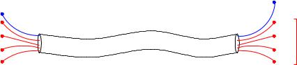
Figure 6.5 illustrates the principle of such a window protocol. These mechanisms make it possible to check for missing parts of the stream of data, acknowledge received data and control the ow of data received from the other party. A checksum in the PDU header allows the receiving party to check that the PDU has not been corrupted in transit. All in all, TCP o ers a reliable connection-oriented service to applications.

38 |
6 BASIC PROTOCOLS IN THE INTERNET |
|
|
|
|
|
|
|
ackr |
|
|
Window size, W |
|
|
|||||
|
|
|
|
|
|
|
|
|
|
|
|||||||
|
|
|
|
|
|
|
|
|
|
|
|
|
r |
|
|
|
|
|
|
|
Received and |
|
|
Octets acceptable |
|
|
|
|
|
||||||
acknowledged octets |
|
|
in following PDU |
|
|
|
|
|
|||||||||
|
|
|
|
|
|
|
|
|
|
|
|
|
|
|
|
|
|
|
|
|
|||||||||||||||
|
|
|
|||||||||||||||
|
|
|
|
|
|
|
|
|
|
|
|
|
|
|
|
|
|
2600 |
2700 |
|
2800 |
2900 |
3000 |
|
3100 |
||||||||||
|
|
|
|
|
|
|
|
|
|
|
|
Sequence numbers |
|||||
Figure 6.5: Operation of the receive window in TCP
Bit |
|
|
|
|
|
|
|
|
|
|
|
|
|
|
|
|
|
|
|
|
|
|
|
|
|
|
|
|
|
|
|||
0 |
|
|
|
|
|
|
|
|
15 |
|
|
|
31 |
||||||||||||||||||||
|
|
|
|
|
|
|
|
|
|
|
|
|
|
|
|
|
|
|
|
|
|
|
|
|
|
|
|
|
|
|
|
|
|
|
|
|
|
Source port no. |
|
Destination port no. |
|
||||||||||||||||||||||||||
|
|
|
|
|
|
|
|
|
|
|
|
|
|
|
|||||||||||||||||||
|
|
|
|
|
|
|
|
|
|
|
|
Sequence number |
|
||||||||||||||||||||
|
|
|
|
|
|
|
|
|
|
|
|
|
|||||||||||||||||||||
|
|
|
|
|
|
|
|
|
|
Acknowledgment number |
|
||||||||||||||||||||||
|
|
|
|
|
|
|
|
|
|
|
|
|
|
|
|
|
|
|
|
|
|
|
|
|
|
|
|
|
|
|
|
|
|
offset |
|
Reserved |
|
URG |
ACK |
PSH |
RST |
SYN |
FIN |
|
|
|
Window size |
|
|||||||||||||||||||
|
Data |
|
|
|
|
|
|
|
|
|
|
|
|
|
|
|
|
|
|
|
|
|
|
|
|
|
|
|
|
|
|
||
|
|
|
|
|
Checksum |
|
|
Urgent pointer |
|
||||||||||||||||||||||||
|
|
|
|
|
|
|
|
|
|
|
|
|
|
|
|
|
|
|
|
|
|
|
|
|
|
|
|
||||||
|
|
|
|
|
|
|
|
|
|
|
|
Header options |
|
|
|
|
|
|
|
Padding |
|
||||||||||||
|
|
|
|
|
|
|
|
|
|
|
|
|
|
|
|
|
|
|
|
||||||||||||||
|
|
|
|
|
|
|
|
|
|
|
|
|
|
|
|
|
|
|
|
|
|
|
|
|
|
|
|
||||||
|
|
|
|
|
|
|
|
|
|
|
|
|
|
|
|
|
|
|
|
|
|
|
|
|
|
|
|
||||||
|
|
|
|
|
|
|
|
|
|
|
|
Data (payload) |
|
|
|
|
|
|
|
|
|
|
|
|
|
|
|||||||
|
|
|
|
|
|
|
|
|
|
|
|
|
|
|
|
|
|
|
|
|
|
|
|
|
|
|
|
|
|
|
|
|
|
|
|
|
|
|
|
|
|
|
|
|
|
|
|
|
|
|
|
|
|
|
|
|
|
|
|
|
|
|
|
|
|
|
|
|
|
|
|
|
|
|
|
|
|
|
|
|
|
|
|
|
|
|
|
|
|
|
|
|
|
|
|
|
|
|
|
|
|
Figure 6.6: Encoding of a TCP PDU
The padding is used to make the length of the header a multiple of 32 bits.
6.3 User Datagram Protocol, UDP |
39 |
The actual PDU is encoded as shown in Figure 6.6. There is only one format for PDUs, but six control ags are used to di erentiate between various purposes for which the PDU may be used:
SYN: Sender is in the process of opening the connection and wishes to synchronise sequence numbers with the other party.
FIN: Sender has no more data to send, and wishes to close connection.
RST: Sender has detected a failure in the operation of the protocol, and aborts the connection.
URG: Indicates that the Urgent Pointer is signi cant, and that it gives the o set of Urgent Data in the PDU.
ACK: Indicates that the Acknowledgement eld is signi cant.
PSH: Push Function.
For example, to set up a connection, the initiator sends a PDU with the SYN ag set and (a proposal for) an initial sequence number, say ns. The called party replies with a PDU with the SYN and ACK ags set, and includes its own (proposal for an) initial sequence number, say nr , and an acknowledgment with the initiator's initial sequence number, (ns + 1). Finally, the initiator responds to this with a PDU with the ACK ag set, with sequence number (ns + 1) and an acknowledgment with the responder's initial sequence number, (nr + 1). Similarly, the FIN ag is used to indicate that the sender hasnished sending data and wishes to close the connection. If the other party has more data to send, it may continue to do so, terminating with a PDU with the FIN ag set to indicate that it, too, has nished sending data. For full details of the operation of the protocol, see [17].
6.3User Datagram Protocol, UDP
UDP is an alternative Transport layer protocol which provides a connectionless-mode service. It is described in RFC768, also known as Internet Standard 6 [15]. UDP uses the same concept of ports as TCP to provide multiplexing of several streams of data between systems with a given pair of IP addresses, and the same restrictions with respect to assigned ports apply. Naturally the protocol contains no features for setting up or closing connections, sequence numbering or ow control, since all these things are meaningless in a connectionless context. Each UDP PDU is sent independently of the others via the underlying IP service.
40 |
7 SIMPLE MAIL TRANSFER PROTOCOL, SMTP |
6.4Internet Application Layer Protocols
A large number of (more or less) standardised protocols are in common use in the Application Layer of the Internet. We shall go into details with two of them later in these notes, but a summary of some of the most important ones and their associated port numbers is given in Table 6.2.
Port |
Protocol |
Application |
20 |
FTP (data stream) |
File transfer |
21 |
FTP (control stream) |
|
23 |
TELNET |
Virtual terminal |
25 |
SMTP |
Mail transfer |
53 |
DNS |
Domain Name Service |
80 |
HTTP |
Web page service |
110 |
POP3 |
Mail retrieval |
119 |
NNTP |
News service |
123 |
NTP |
Clock synchronisation |
143 |
IMAP |
Interactive mail retrieval |
389 |
LDAP |
Lightweight directory access |
|
|
|
Table 6.2: Internet Application Layer protocols
You can easily nd a list of assigned port numbers and the associated applications if you have access to a system which uses a Unix-based operating system, such as Linux or Solaris: just look in the /etc/services le. A complete and up-to-date list is maintained by IANA, the authority which registers the numbers, and can be seen on the Web page http://www.iana.org/assignments/port-numbers.
7Simple Mail Transfer Protocol, SMTP
The rst detailed example of an Internet Application layer protocol which we shall look at is SMTP, of which a full description can be found in Internet RFC821, which forms part of Internet Standard 10 [18]. The purpose of SMTP is to transfer mail messages composed by a user for transmission to one or more other users. In fact, in the Internet world, mail is not sent directly to the recipient user (who of course might not be logged on when the message is sent), but is transferred to a mailbox owned by the recipient instead. At some convenient time, the recipient needs to use another protocol to retrieve his or her mail from the mailbox so that it can be read (or whatever needs to be done with it). The two commonest protocols for retrieving mail from a mailbox are: