

Sharp R.The poor man's guide to computer networks and their applications.2004
.pdf21
An ACK PDU to be sent from destination d to source s will be formatted as shown in Figure 4.6(b), where t is the 8-bit sequence 10000010, s and d are represented by 32-bit IP addresses, and c is a 32-bit checksum eld evaluated over all the other elds of the PDU according to the CRC-32 algorithm.
More complicated rules of procedure and a greater variety of PDU formats can be expected to occur in more realistic examples. In such cases, a more formal notation than ordinary prose is often preferred, in order to achieve a concise description with a high degree of precision. Most such notations are based on one of two principles for describing the behaviour of the protocol:
1.In terms of a state machine, which reacts to incoming events and produces outgoing events. Two well-known internationally standardised languages based on this principle are SDL (standardised by the International Telecommunications Union, ITU-T [29])and ESTELLE (standardised by the International Organization for Standardization, ISO [10]).
2.In terms of a set of interacting processes which exchange messages. Process algebraic languages such as CCS [30] and CSP [7], and the language LOTOS (standardised by ISO [9]) are typical examples of notations which have been used with this approach.
5Network Technology
These notes will not deal in any depth with network technology, and if you need to know more you will need to look at some of the more technology-oriented references. However, we shall try to explain what some of the commonly used terms mean, so that you understand what the salesman is talking about when he calls to sell you some network equipment.
Referring back to the introductory section on computer networks, you may be wondering what exactly the communication nodes and the end systems consist of, and how all this ts into the scheme of the OSI Reference Model (or its Internet variant). One typical answer is shown in Figure 5.1. In this example, the communication nodes implement the OSI layers up to and including the Network layer, and are thus responsible for:
Accepting PDUs on an incoming link from another node at the Data Link level.
Routing these PDUs to an outgoing link at the Network level.
Transmitting PDUs on an outgoing link to another node at the Data Link level.
Sending or receiving PDUs at the Data Link level of course requires the node to activate the facilities of the Physical layer in order to deal with the task of signalling on the physical medium.

22 |
|
|
|
|
|
|
|
|
|
|
5 |
NETWORK TECHNOLOGY |
|||
End system |
|
|
|
Communication nodes |
|
|
End system |
||||||||
|
A |
|
|
|
|
|
|
|
|
|
|
|
B |
||
|
|
|
|
|
|
|
|
|
|
||||||
|
|
|
|
|
|
|
|
|
|
||||||
|
|
|
|
|
|
|
|
|
|
|
|
|
|
|
|
|
A |
|
|
|
|
|
|
|
|
|
|
|
|
A |
|
|
|
|
|
|
|
|
|
|
|
|
|
|
|
|
|
|
P |
|
|
|
|
|
|
|
|
|
|
|
|
P |
|
|
|
|
|
|
|
|
|
|
|
|
|
|
|
|
|
|
S |
|
|
|
|
|
|
|
|
|
|
|
|
S |
|
|
|
|
|
|
|
|
|
|
|
|
|
|
|
|
|
|
T |
|
|
|
|
|
|
|
|
|
|
|
|
T |
|
|
|
|
|
|
|
|
|
|
|
|
|
|
|
|
|
|
N |
|
N |
|
|
N |
|
|
N |
|
N |
|
|||
|
|
|
|
|
|
|
|
|
|
|
|
|
|
|
|
|
D |
|
D |
|
D |
|
D |
|
D |
|
D |
D |
|
D |
|
|
|
|
|
|
|
|
|
|
|
|
|
|
|
|
|
|
Ph |
|
Ph |
|
Ph |
|
Ph |
|
Ph |
|
Ph |
Ph |
|
Ph |
|
|
|
|
|
|
|
|
|
|
|
|
|
|
|
|
|
Medium
Figure 5.1: Layers in the communication nodes and end systems in a computer network
5.1Routers
A node which implements the layers up to the Network layer and is capable of choosing a suitable route for sending an NPDU on to its destination is known as a router. Although this cannot be seen in Figure 5.1, a router will in general have a larger number of links to deal with than just two { otherwise there would be no need to make any choices about which route to take. You should refer back to Figure 3.3 for a view of the computer network which should make this more clear.
When routing decisions have to be made, most routers are also able to decide that certain PDUs are not to be passed on to the destination which has been speci ed for them. This activity of removing irrelevant PDUs is known as ltering. Typical reasons for doing this include:
The router can determine that the destination cannot be reached via any of the outgoing links from the router.
The router can determine that data from the given (or apparent) source is not desired by the speci ed destination system.
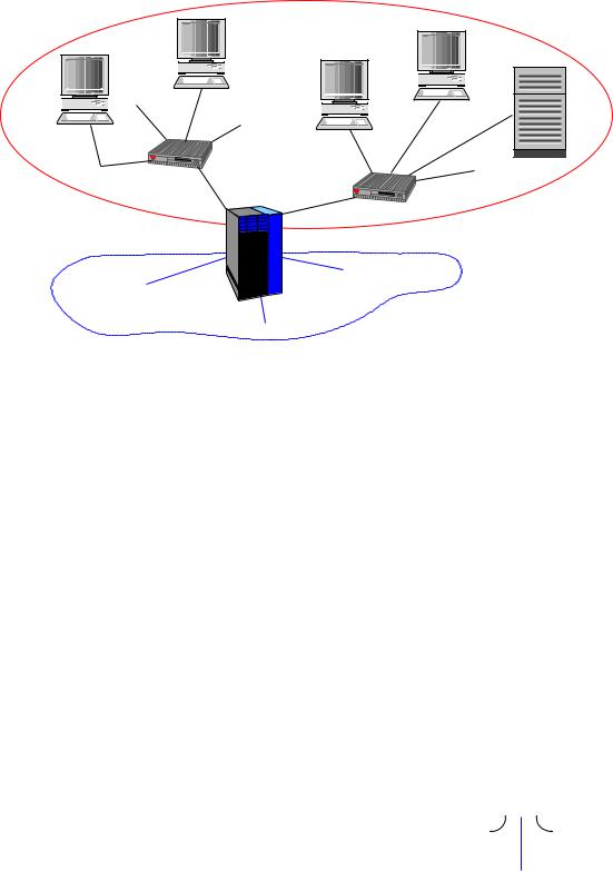
A router which can be programmed to refuse to pass tra c from certain sources or addressed to certain destinations or for use by certain applications is often simply known as a (packet) lter. A typical arrangement is as shown in Figure 5.2, where a combined router and lter is placed on the boundary of a company's internal network, and acts tolter tra c passing between this network and the Internet. Since this type of ltering also acts to protect the systems in the network from certain types of ill-intentioned tra c,ltering is one of the functions typically found in a rewall intended to protect a network
5.2 Bridges |
23 |
Internal network
Router + Filter
To network C
To network A
Internet
To network B
Figure 5.2: A combined router and lter on the boundary between an internal network and the Internet.
or subnet from attack by intruders such as hackers. Many modern routers in fact combine the functions of a router and a rewall in the same piece of equipment.
5.2Bridges
From Figure 5.1 you might get the impression that there is always a direct connection (via the Data Link layer) between any two routers in a network. This is not entirely true. Often the subnet (the part of the network) which lies between two routers is, for practical reasons, divided into a series of segments which are joined together by bridges. These implement a junction between two parts of the network in the Data Link layer, as illustrated in Figure 5.3.
Typical functions of a bridge are:
To lter tra c passing in the subnet, so that parts of the tra c which do not need to pass the bridge in order to reach their destination are prevented from doing so. The purpose of doing this in the Data Link layer is to prevent unnecessary tra c from overloading the individual segments of the network. Since the bridge operates in the Data
|
|
D |
|
|
|
|
|
|
|
|
|
|
|
|
|
Ph |
|
Ph |
|
|
|
|
|
|
|
|
|
|
|
|
|
|
|
|
Medium |
Medium |
|||||
Segment 1 |
Segment 2 |
|||||
Figure 5.3: A bridge between two network segments
24 |
5 NETWORK TECHNOLOGY |
Link layer, the ltering decision is based on the addresses used to identify systems in this layer (rather than the Network addresses used by the router).
To adapt between di erent conventions for data transmission used in the Physical layer in di erent segments which use the same Data Link protocol (see Section 5.3 below). For example, one segment may use electrical signalling on twisted pair cable, while the neighbouring segment uses a bre optic connection.
A bridge usually possesses no real routing capability { the kind of yes/no decisions made by a lter do not qualify in this respect. However, a bridge will sometimes be a collecting point for several segments of a subnet, and in such a case it will also provide a rudimentary form of routing, in order to pass data on to the appropriate segment.
5.3LAN Technologies
A LAN is intended to o er data communication facilities over a limited area, such as a single building, a company premises or an institution such as a university department or an entire university. Over such a limited area, it becomes technically feasible to let all the nodes attached to the network have shared access to a common medium, which can be based on cables or wireless facilities covering the area concerned. The Physical Layer technologies are therefore chosen to suit such media, and the Data Link protocols control access to the shared medium. Traditionally, the LAN Data Link layer is conceptually divided into two sub-layers:
1.A lower, technology-dependent Medium Access Control (MAC) sublayer, of which we shall look at two examples in detail below.
2.An upper Logical Link Control (LLC) sublayer, which is intended to provide a technology-independent Data Link service based on a variety of MAC sublayers.
Most LAN MAC sublayers in current use follow one of the IEEE standards from the socalled 802.x series, which have been more or less taken over lock, stock and barrel by ISO to form the various parts of the ISO8802 standard. These are summarised in Table 5.1. You will notice that several numbers are missing in the table. Some of the missing items cover general topics, such as LAN architecture (802.1), Logical Link Control (802.2) and security (802.10); others have just never become standards. Many of the standards also come in several variants, for di erent Physical Layer data rates or di erent physical media (or both). We shall see some examples of this in the following sections.
5.3.1CSMA/CD Technology
CSMA/CD technology is nowadays the dominant technology for wired LANs, i.e. local area networks where the signals are transmitted via some kind of cable which is laid out round
5.3 LAN Technologies |
25 |
IEEE ISO Technology
802.38802-3 Carrier Sense Multiple Access/Collision Detect (CSMA/CD)
802.48802-4 Token Bus
802.58802-5 Token Ring
802.68802-6 Distributed Queue Dual Bus (DQDB)
802.98802-9 Integrated Services (IS) LAN
802.118802-11 Wireless LAN
802.128802-12 Demand-priority Access
802.158802-15 Wireless Personal Area Networks (WPAN)
802.168802-16 Fixed Broadband Wireless Access (FBWA)
Table 5.1: IEEE and ISO standardised LAN technologies
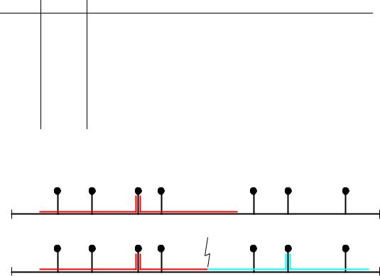
A B C D E F G
(a)
A B C D E F G
(b) |
Figure 5.4: Propagation of signals along a shared bus or cable.
(a)Signals from a single sender (C) propagate along the bus in both directions.
(b)If two nodes (C, F) try to send at the same time, their signals collide and the transfer of data does not succeed.
the building(s) to be covered. Originally, the cable was a thick coaxial cable which could carry data at 10 Mbit/s; subsequently, thinner coaxial cables and shielded twisted pairs of wires have been used, and data rates from 1 to 1000 Mbit/s have become readily available. The original technology was developed by a consortium of companies, and registered under the trade name EthernetTM. This name is commonly (but not very correctly) used as a synonym for CSMA/CD, so for example the technology for operating CSMA/CD at 1000 Mbit/s is often referred to as Gigabit Ethernet.
CSMA/CD is strictly speaking a MAC protocol, for gaining access to a shared broadcast medium. The cable works in this respect like a computer bus, so signals from any node attached to the medium will propagate in all directions out from the sender until they reach the end of the bus. This is illustrated in Figure 5.4(a) If two nodes try to send at the same time, a collision occurs between their signals, as shown in Figure 5.4(b), with the result that the intended receivers cannot make sense of the message.
This problem is a general one in systems based on the use of a shared broadcast medium,
26 |
5 NETWORK TECHNOLOGY |
Position |
|
|
|
|
|
|
|
|
|
CD time |
CE time |
|
Medium |
Transmission starts |
|||
|
|
|
|
Random |
|
occupied |
when medium free |
|
|
|
retransmission delay |
|
|
|
|||
|
|
|
|
|
|
|||
A |
! |
|
|
|
|
|
" |
|
|
|
|
|
|
|
|
|
|
|
|
|
|
|
|
|
# |
|
B |
|
|
|
Random |
|
|
|
|
|
|
|
|
|
|
|||
|
|
|
retransmission delay |
Transmission starts |
|
|
||
|
CD time |
CE time |
|
|
||||
|
|
|
when medium free |
|
Time |
|||
|
|
|
|
|
|
|||
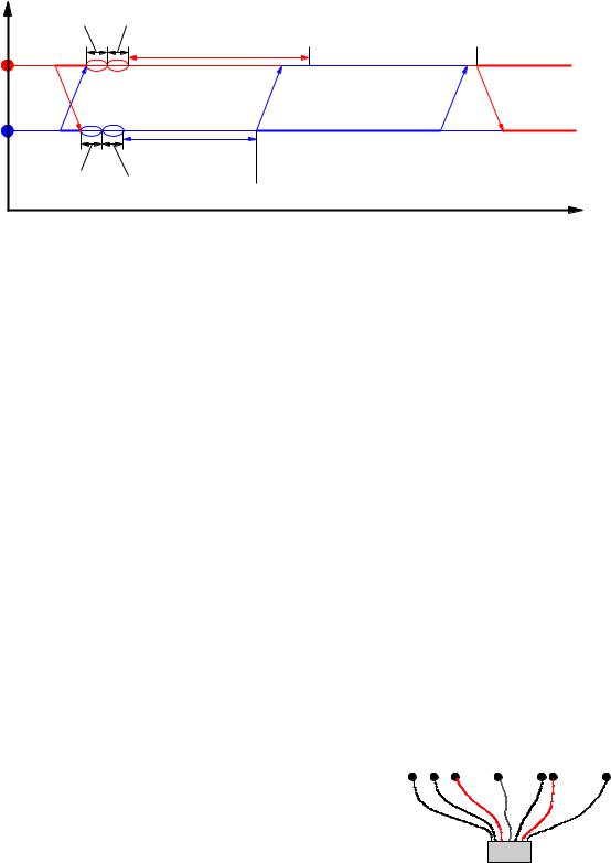
Figure 5.5: Collision Detection and retransmission in the CSMA/CD MAC protocol
where the nodes e ectively compete to get access to the medium. The technical term for this type of competition is contention. The CSMA/CD protocol introduces two rules for regulating access to the medium to counteract the e ects of contention:
CSMA: Listen before sending. If the medium is occupied (indicated by the presence of signals from other nodes), then wait until it is free.
CD: Listen while sending. If signals from other nodes are also detected, then a collision has occurred because several nodes have found the medium free at the same time. Stop sending and wait a random time before trying again.
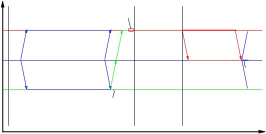
The random time is assumed to be chosen di erently for each node, so there is a high statistical probability that one of the nodes will nd the medium free next time it tries, though obviously this probability gets smaller and smaller as the intensity of the tra c increases. Figure 5.5 illustrates what happens if just two nodes try to send at the same time. In the gure, the CD time is the time required for a node to detect that a collision has taken place. Once it has detected this, it sends a special Collision Enforcement (CE) signal on the medium to inform all other nodes that the current transmission is worthless. This signal lasts during the CE time. After sending the CE signal, the colliding nodes each wait a randomly chosen interval before trying again.
The discussion here has assumed that the shared medium, |
|
|
|
|
to which the nodes try to gain access, actually is a ca- |
|
Nodes |
|
|
ble which runs round the building. This is not always |
A B C |
D |
E F |
G |
convenient, and many modern Ethernet installations use |
|
|
|
|
a switch, instead of a passive cable, to connect a set of |
|
|
|
|
nodes, as illustrated in Figure 5.6. This technology is of- |
|
|
|
|
ten referred to as switched Ethernet. If, for example, node |
|
|
|
|
C in the gure transmits a PDU addressed to node F, then |
|
Switch |
|
|
the switch will try to set up a path directly from C to F. |
|
|
|
|
Figure 5.6: A switch connecting seven nodes

5.3 LAN Technologies |
27 |
If F is busy sending to or receiving from another node, the path cannot be set up, and C must try again later. But if the path can be set up, then C can send the PDU to F at the full data rate allowed by the network technology. The switch enables several pairs of nodes to talk to one another using the full network bandwidth at the same time, thus avoiding much of the contention which arises in the shared medium of a traditional shared Ethernet. Of course, there will still be contention when several senders simultaneously try to reach the same destination, but if this only happens rarely then switch technology allows you to build a network with an bigger overall data carrying capacity than a shared Ethernet operating at the same data rate.
5.3.2Wireless LAN Technology
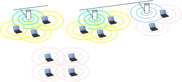
Wireless LAN technology has become very important in recent years, as it o ers a convenient way to achieve not just distributed computing but mobile computing, where the computing systems are allowed to move physically from one site to another. In a Wireless LAN, signals from transmitting nodes propagate in all directions4, and can be picked up by other nodes which are within a certain range, usually somewhere between 25m (inside a building) and 300m (in the open air). There are three basic styles of Wireless LAN, which are illustrated in Figure 5.7. In the BSS architecture, a central, immobile Access Point (AP) performs coordinating functions, and is used as an intermediate station for all tra c between the set of mobile nodes which are within its range. In the ESS architecture, several Access Points are connected by a wired network, thus permitting mobile nodes to keep in contact, as long as they are within range of at least one Access Point. Tra c intended for the di erent Access Points is typically sent on di erent radio channels in the frequency band in use. In the Ad hoc architecture, there is no Access Point, and all the mobile nodes communicate directly with one another.
Practical computer systems which make use of Wireless LAN technology are nowadays almost all based on the IEEE 802.11 standard5. This prescribes two alternative MAC protocols, of which the most commonly used is closely related to the CSMA/CD protocol described above, and is known as the Carrier Sense Multiple Access/Collision Avoidance (CSMA/CA) protocol. The CA part of the name refers to a slightly di erent mechanism used to deal with contention: Instead of letting all nodes with a pending transmission send as soon as the channel seems to be unoccupied, and trying to detect collisions, the nodes use a time slot mechanism to choose an instant at which to test whether the channel really is unoccupied. Each node with a pending transmission chooses a slot at random, and the one which chooses the lowest number nds the channel really is unoccupied and thus wins the \race" to be allowed to use the channel. In a wireless network, this is not quite foolproof, as stations may not all be able to hear one another, so the receiving station
4At least in principle, since sometimes the sending or receiving antenna is directional. 5Actually, it is a family of standards, as we shall see later.
28
(a) Wired |
LAN |
|
AP |
||
|
5 NETWORK TECHNOLOGY
(b) |
Wired |
LAN |
AP |
|
|||
|
|
||
|
AP |
|
|
(c)
Figure 5.7: Basic architectures of Wireless LANs
(a)Basic Service Set (BSS)
(b)Extended Service Set (ESS)
(c)Ad hoc (IBSS or peer-to-peer)
must send a positive acknowledgment for receipt of a PDU. If the sender receives no ACK, it retransmits the PDU after a new random delay. This is illustrated in Figure 5.8.
The basic 802.11 Wireless LAN standard describes the operation of the Medium Access protocol and three variants of the Physical Layer protocol for:
Operation in the 2.4 GHz Industrial, Scienti c and Medical (ISM) wireless band, using the frequency-hopping spread spectrum (FHSS) technique to achieve a 1 Mbit/s data rate.
Operation in the 2.4 GHz wireless band, using the direct sequence spread spectrum (DSSS) technique to achieve a 1 or 2 Mbit/s data rate.
Operation in the infrared band to achieve a 1 or 2 Mbit/s data rate.
As time has passed, this standard has accumulated a considerable number of additional variants and amendments, indicated by extra letters after the number. Some of the ones you are most likely to meet are:
802.11a Describes the operation of the Physical Layer in the 5 GHz wireless band, to achieve a data rate up to 54 Mbit/s.
802.11b Describes the operation of the Physical Layer in the 2.4 GHz wireless band, to achieve a 1, 2, 5.5 or 11 Mbit/s data rate.
802.11e Enhancements to the Medium Access protocol to provide QoS.
29
Position
A
B
C
Slot 9
|
Medium |
|
|
|
IFS |
|
occupied |
|
|
|
|
|
|
|
|
|
|
|
|
|
|
||
|
|
||||
|
|
||||
|
|
|
|
||
|
|
|
|||
|
|
|
|
||
|
|
|
|||
|
|
|
|
||
|
|
|
|||
|
|
|
|
||
|
|
|
|||
|
|
|
|
||
|
|
|
|||
|
|
|
|
||
|
|
|
|
|
|
|
|
|
|
|
|
|
|
|
|
|
|
|
|
|
|
|
|
|
|
|
|
|
|
|
|
|
|
|
|
|
|
|
|
|
|
|
|
ACK |
|||
Medium free. |
|
|
|
|
|
B’s transmission starts |
|
|
|
|
|
|
|
|
|
|
|
Slot 0 |
Slot 1 |
Slot 2 |
Slot 3 |
Transmission starts if medium free
during A’s chosen slot

ACK

4Slot Time
Figure 5.8: Contention Avoidance in the CSMA/CA protocol
IFS is the Inter-Frame Space, a period of silence which separates one transmission from the rst reservation slot for the next transmission.
802.11g Describes an extension to achieve data rates of 22 or 54 Mbit/s in the 2.4 GHz wireless band.
802.11h Describes extensions to achieve Spectrum and Transmit Power Management, in order to use the 5 GHz band in Europe.
802.11i Describes security enhancements to the Medium Access protocol.
In Europe, important parts of the 5 GHz wireless band are reserved for other purposes, so the 802.11a technology is unlikely to be used (even if 802.11h is followed). Instead, the high data rates o ered by 802.11a are likely to be achieved by using equipment which follows the 802.11g standard.
6Basic Protocols in the Internet
In these notes, most of the examples will be concerned with the kind of protocols used in the Internet. An overview of some of the best known ones can be seen in Figure 6.1. There are no special Internet protocols assigned for use in the Data Link or Physical layers. The protocols in these layers are very technology dependent, and the appropriate choice will depend on the environment in which the network is to operate. For example, if communication takes place within a single building or building complex, it would be natural to base the network on LAN technology, and one of the IEEE 802.x protocols

30 |
6 BASIC PROTOCOLS IN THE INTERNET |
APPLICATION
TRANSPORT
Direct support to appl. processes.
Transformation of data to syntactic form acceptable to local processes.
File transfer: |
FTP |
E-mail: |
SMTP, POP, IMAP |
Web access: |
HTTP |
News access: NNTP
Clock synchronisation: NTP
End-to-end transfer of data.
Connection-mode: TCP
Connectionless-mode: UDP
Transfer of data between arbitrary NETWORK systems in arbitrary networks.
Connectionless-mode: IP
DATA LINK
PHYSICAL
Transfer of data between neighbour (or other directly connected) systems.
Transfer of physical data units (bits) between data link entities.
PHYSICAL MEDIUM
Figure 6.1: Protocols in the Internet layered architecture