

AMBA Test Methodology
6.8.5Changing burst direction
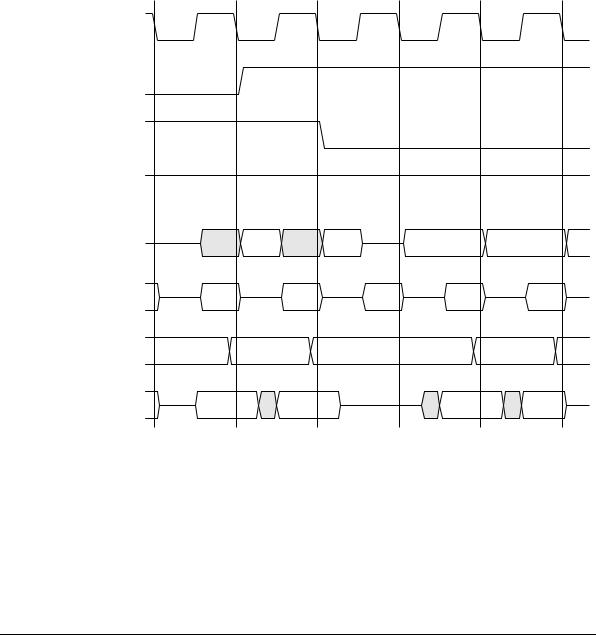
Figure 6-19 below shows a burst changing direction from read to write.
|
C0 |
TCLK |
|
TREQA |
|
TREQB |
|
TACK |
|
TBUS |
|
BTRAN[1:0] |
|
BA |
A |
BD |
|
C1 |
C2 |
|
C3 |
C4 |
Read |
Read |
|
Write |
Write |
vector 1 |
vector 2 |
|
vector 1 |
vector 2 |
S-TRAN |
A-TRAN |
S-TRAN |
S-TRAN |
S-TRAN |
A + 4 |
|
A + 8 |
|
A + C |
Read |
Read |
|
Write |
Write |
data 1 |
data 2 |
|
data 1 |
data 2 |
Figure 6-19 Changing burst direction
6-36 |
© Copyright ARM Limited 1999. All rights reserved. |
ARM IHI 0011A |

AMBA Test Methodology
6.8.6Exiting test mode
Figure 6-20 shows an exit from test mode.
|
C0 |
|
TCLK |
|
|
TREQA |
|
|
TREQB |
|
|
TACK |
|
|
TBUS |
Write |
|
vector |
||
|
||
BTRAN[1:0] |
A-TRAN |
|
BA |
A |
|
BD |
Write |
|
data |
||
|
C1 |
C2 |
C3 |
C4 |
Address |
|
|
|
vector |
|
|
|
|
|
|
Normal operation |
A-TRAN |
|
|
|
Figure 6-20 Exiting test mode
ARM IHI 0011A |
© Copyright ARM Limited 1999. All rights reserved. |
6-37 |

AMBA Test Methodology
6-38 |
© Copyright ARM Limited 1999. All rights reserved. |
ARM IHI 0011A |

Index
The items in this index are listed in alphabetic order. The references given are to page numbers.
A |
|
AHB 3-1 |
1-7 |
|
|
APB 5-1 |
|
2-8 |
|
|
Active state |
4-56 |
arbiter |
|
|
address bus |
|
|
|||
arbitration signals |
2-5 |
bridge |
5-8 |
|
|
|
||||
Address and control signals |
decoder |
1-8 |
1-7 |
bridge interface diagram |
5-8 |
|||||
ASB |
4-27 |
introduction to |
bridge transfer |
5-9 |
|
|||||
master |
1-7 |
|
|
components |
5-7 |
|
|
|||
timing |
4-29 |
|
|
|
|
|||||
operation |
3-5 |
|
|
in a typical AMBA system 5-3 |
||||||
Address bus |
|
|
|
|||||||
|
signal list |
2-3 |
|
|
introduction to |
1-10 |
|
|||
AHB |
2-3 |
|
|
|
||||||
signal prefixes |
2-2 |
|
read data bus |
2-8 |
|
|
||||
APB |
2-8 |
slave 1-7 |
|
|
read transfers |
5-6 |
|
|
||
ASB |
2-6, 4-27 |
AHB/ASB or APB, when to use 1-13 |
select |
2-8 |
|
|
|
|||
Address decoding |
AMBA signal names |
2-2 |
signal list 2-8 |
|
|
|||||
AHB |
3-19 |
signal prefixes |
2-2 |
|
||||||
|
|
|
|
|
||||||
ASB |
4-14 |
AMBA system, typical |
1-4 |
slave |
5-11 |
|
|
5-11 |
||
Address vectors 6-8, 6-28 |
AMBA test interface |
6-2 |
slave interface diagram |
|||||||
strobe |
2-8 |
|
|
|
||||||
Address-only transfers 4-10, 4-59 |
AMBA test methodology |
6-1 |
|
|
|
|||||
timing parameters |
5-7, 5-10 |
|||||||||
AGNTx 2-6, 4-44 |
|
|
|
|
transfer direction |
2-8 |
|
|||
|
|
|
|
|
|
write data bus |
2-8 |
|
||
|
|
|
|
|
|
write transfers |
5-5 |
|
||
|
|
|
|
|
|
Arbiter |
|
|
|
|
|
|
|
|
|
|
AHB |
1-7 |
|
|
|
|
|
|
|
|
|
ASB |
1-9, 4-20, 4-71 |
|
||
|
|
|
|
|
|
Arbitration and reset signals |
4-60 |
|||
ARM IHI 0011A |
© Copyright ARM Limited 1999. All rights reserved. |
Index-i |

Index |
|
|
|
|
|
|
|
Arbitration signals |
|
|
|
||||
AHB |
|
2-5 |
|
|
|
|
|
ASB |
|
4-44 |
|
|
|
||
Arbitration, AHB |
3-28 |
|
|
||||
AREQx |
2-6, 4-44 |
|
|
||||
ASB |
4-1 |
|
|
|
|
|
|
and APB |
4-3 |
|
|
||||
arbiter |
1-9, 4-20, 4-71 |
|
|||||
arbiter interface diagram |
4-71 |
||||||
arbiter timing parameters |
4-73 |
||||||
bus master |
4-52 |
|
|
||||
bus master interface diagram 4-52 |
|||||||
bus slave |
4-47 |
|
|
||||
bus slave interface |
4-47 |
|
|||||
components |
4-46 |
|
|
||||
decoder |
1-9, 4-63 |
|
|
||||
decoder interface diagram |
4-64 |
||||||
decoder timing diagrams |
4-68 |
||||||
decoder timing parameters |
4-69 |
||||||
description |
4-4 |
|
|
||||
introduction to |
1-9 |
|
|||||
master |
1-9 |
|
|
|
|||
signal description 4-25 |
|
||||||
signal list |
2-6 |
|
|
||||
signal prefixes |
2-2 |
|
|||||
slave |
|
1-9 |
|
|
|
|
|
slave bus interface state |
|
||||||
|
|
|
|
machine |
4-48 |
||
test sequence |
6-27 |
|
|
||||
transfers |
4-6 |
|
|
|
|||
B |
|
|
|
|
|
|
|
BA |
2-6, 4-27 |
|
|
|
|
||
Back to back transfers |
5-18 |
|
|||||
Backbone bus |
1-4 |
|
|
||||
Basic transfers |
3-6 |
|
|
||||
BCLK |
|
2-6, 4-25 |
|
|
|
||
BD |
2-6, 4-40 |
|
|
|
|
||
BERROR |
2-6, 4-36 |
|
|
||||
BLAST |
2-6, 4-36 |
|
|
||||
BLOK |
2-6, 4-45 |
|
|
|
|||
BnRES |
2-6, 4-23, 4-25 |
|
|||||
BPROT |
2-7, 4-28 |
|
|
||||
encoding |
4-28 |
|
|
||||
BSIZE |
2-7, 4-28 |
|
|
|
|||
encoding |
4-28 |
|
|
||||
BTRAN |
2-7, 4-26 |
|
|
||||
encoding |
4-26 |
|
|
||||
timing |
4-27 |
|
|
|
|||
Burst operation |
1-6, 3-11 |
|
|||||
Burst type, AHB |
2-3 |
|
|
||||
Burst vectors |
6-10, 6-22 |
|
|||||
Bursts |
|
|
|
incrementing 3-12 |
|||
of read transfers |
5-15 |
||
of write transfers |
5-17 |
||
undefined-length 3-16 |
|||
wrapping |
3-12 |
|
|
Bus |
|
|
|
backbone |
1-4 |
|
|
choosing |
1-12 |
|
|
peripheral |
1-12 |
|
|
Bus clock |
|
|
|
AHB |
2-3 |
|
|
APB |
2-8 |
|
|
ASB |
2-6 |
|
|
Bus cycle |
1-6 |
|
|
Bus grant |
4-44 |
|
|
AHB |
2-5 |
|
|
ASB |
2-6 |
|
|
Bus interface state machine, ASB 4-54
Bus lock |
4-45 |
|
||
Bus master |
|
|
|
|
ASB |
|
4-52 |
|
|
default |
|
4-22 |
|
|
granted state machine |
4-53 |
|||
handover |
3-29, 4-20 |
|||
interface, ASB 4-52 |
||||
main state machine |
4-55 |
|||
timing diagrams, ASB |
4-57 |
|||
timing parameters, ASB 4-60 |
||||
Bus request |
|
4-44 |
|
|
AHB |
|
2-5, 3-28 |
|
|
ASB |
|
2-6 |
|
|
Bus retract |
|
|
4-36 |
|
Bus slave interface, ASB |
4-47 |
|||
Bus transfer |
|
1-6 |
|
|
Busidle state |
4-56 |
|
||
BWAIT |
2-7, 4-36 |
|
||
BWRITE |
|
2-7, 4-27 |
|
|
encoding |
4-27 |
|
||
C
Choosing the right bus 1-12
Clock, ASB 4-25 |
|
Control signals |
3-17 |
Control vectors |
6-9, 6-14, 6-21, 6-29 |
bit definitions |
6-25 |
D
Data bus |
|
AHB |
3-25 |
ASB |
2-6, 4-40 |
Deadlock |
3-37 |
Decode cycles 4-33, 4-65
Decoder |
|
|
AHB |
1-8 |
|
ASB |
1-9, 4-63 |
|
state machine |
4-65, 4-67 |
|
with decode cycles 4-33, 4-65 |
||
without decode cycles 4-34, 4-67 |
||
Default bus master |
4-22 |
|
Direction of transfer |
|
|
APB |
2-8 |
|
ASB |
2-7 |
|
Done response 4-16, 4-48 |
|
DSEL |
4-33 |
DSELx |
2-7 |
E
Early burst termination |
3-12 |
||
Electrical characteristics |
1-14 |
||
Enable state |
5-5 |
|
|
Enter test mode |
6-8, 6-17, 6-27 |
||
Error response |
4-16, 4-36, 4-48 |
||
ASB |
2-6 |
|
|
Exit from reset |
4-23 |
|
|
Exit test mode |
6-11, 6-24, 6-37 |
||
External test interface |
6-4 |
||
G
Grant signal, AHB 3-28
Granted state machine 4-53
H
HADDR |
2-3 |
Handover |
3-29 |
Handover state 4-56 |
|
Handover, bus master 4-20
HBURST |
|
2-3 |
HBUSREQx |
2-5, 3-28 |
|
HCLK |
2-3 |
|
HGRANTx |
2-5, 3-28 |
|
HLOCKx |
|
2-5, 3-28 |
HMASTER |
2-5 |
|
HMASTLOCK 2-5 |
||
Hold state |
4-56 |
|
HPROT |
2-3, 3-17 |
|
HRDATA |
2-4, 3-25 |
|
HREADY |
2-4, 3-20 |
|
HRESETn |
2-3 |
|
HRESP |
2-4, 3-20 |
|
HSELx |
2-4 |
|
Index-ii |
© Copyright ARM Limited 1999. All rights reserved. |
ARM IHI 0011A |

HSIZE 2-3, 3-17 |
|
HSPLITx |
2-5 |
HTRANS |
2-3 |
HWDATA |
2-4, 3-25 |
HWRITE |
2-3, 3-17 |
I
Idle state 4-56, 5-4 |
|
|
Incremental addressing |
6-7 |
|
Incrementing burst |
3-12 |
|
Interfacing |
|
|
APB to AHB |
5-14 |
|
APB to ASB |
5-20 |
|
revD peripherals |
5-22 |
|
L
Last response 4-17, 4-36, 4-48 ASB 2-6
Lock signal, AHB 3-28
Locked sequence, AHB 2-5 Locked transfers
AHB |
2-5 |
ASB |
2-6, 4-22 |
M
Master
AHB 1-7
ASB 1-9 Master number AHB 2-5
Multi-master operation, ASB 4-19 Multiple transfers 3-8
N
Nonsequential transfers 4-7, 4-57
P
PADDR 2-8
PCLK 2-8
PENABLE 2-8
Peripheral bus 1-12 Peripheral test harness 6-2
PRDATA |
2-8 |
PRESETn |
2-8 |
Protection control |
|
AHB |
2-3, 3-17 |
ASB |
2-7 |
Protection signals |
|
ASB |
4-28 |
PSELx 2-8
PWDATA 2-8
PWRITE 2-8
R
Read data bus |
|
|
AHB |
2-4, 3-25 |
|
APB |
2-8 |
|
Read test vectors |
6-10 |
|
Read transfers |
6-20 |
|
APB |
5-6, 5-14 |
|
burst of |
5-15 |
|
to ASB |
5-21 |
|
Reset 4-25 |
|
|
AHB |
2-3 |
|
APB |
2-8 |
|
ASB |
2-6 |
|
exit from |
4-23 |
|
Reset operation, ASB 4-23 |
||
Response encoding |
3-21 |
|
Retract response |
4-17, 4-48 |
|
Retract state |
4-56 |
|
Retry transfers |
3-38 |
|
Rev D peripherals |
5-22 |
|
S
Select, APB |
2-8 |
|
Sequential transfers |
4-8, 4-58 |
|
Setup state |
5-4 |
|
Signal list |
|
|
AHB |
2-3 |
|
APB |
2-8 |
|
ASB |
2-6 |
|
Signal names |
|
|
AMBA |
2-2 |
|
Signal prefixes |
|
|
AHB |
2-2 |
|
APB |
2-2 |
|
ASB |
2-2 |
|
Size encoding 3-17 |
|
|
Size of transfer |
|
|
ASB |
2-7 |
|
Slave |
|
|
AHB |
1-7 |
|
ASB |
1-9 |
|
transfer response |
3-20 |
|
Slave select |
|
|
AHB |
2-4 |
|
ASB |
2-7, 4-33 |
|
Split completion request, AHB 2-5 Split transfers 3-35, 3-37
State diagram
TIC 6-12
Index
State machine
ASB slave bus interface 4-48
bus interface, ASB |
4-54 |
|
bus master, main |
4-55 |
|
decoder |
4-65, 4-67 |
|
Strobe, APB |
2-8 |
|
T
TACK |
6-4 |
|
|
|
|
|
TBUS |
6-5 |
|
|
|
|
|
TCLK |
6-5 |
|
|
|
|
|
Technology independence |
1-14 |
|||||
Termination, early burst |
3-12 |
|||||
Terminology |
1-6 |
|
|
|||
Test |
|
|
|
|
|
|
transfer parameters |
6-7 |
|||||
Test acknowledge |
6-4 |
|
||||
Test bus |
|
6-5 |
|
|
|
|
Test bus request |
6-4 |
|
||||
Test clock |
6-5 |
|
|
|
||
Test harness |
6-2 |
|
|
|
||
Test Interface Controller |
|
|||||
ASB |
|
6-25 |
|
|
|
|
ASB, state diagram |
6-25 |
|||||
Test Interface Controller (TIC) 6-3, 6-7 |
||||||
Test Interface Controller state |
||||||
|
diagram |
6-12 |
||||
Test mode |
|
|
|
|
|
|
entering |
6-8, 6-17, 6-27 |
|||||
exiting |
6-11, 6-24, 6-37 |
|||||
Test sequence |
6-17 |
|
|
|||
ASB |
|
6-27 |
|
|
|
|
Test vector types |
6-6 |
|
||||
TIC 6-3, 6-7 |
|
|
|
|
||
Timing diagrams |
|
|
|
|||
APB bridge |
5-9 |
|
||||
APB slave |
5-12 |
|
||||
ASB arbiter |
4-72 |
|
||||
ASB bus slave |
|
4-49 |
||||
ASB decoder |
4-68 |
|
||||
Timing parameters |
|
4-69 |
|
|||
APB |
|
5-7, 5-10 |
|
|
||
APB slave |
5-13 |
|
||||
ASB |
|
4-46 |
|
|
|
|
ASB arbiter |
4-73 |
|
||||
ASB bus master |
4-60 |
|||||
ASB bus slave |
|
4-50 |
||||
Timing specification |
1-14 |
|||||
Transfer direction |
|
|
|
|||
AHB |
2-3, 3-17 |
|
|
|||
APB |
|
2-8 |
|
|
|
|
ASB |
|
2-7 |
|
|
|
|
Transfer direction, ASB |
4-27 |
|||||
ARM IHI 0011A |
© Copyright ARM Limited 1999. All rights reserved. |
Index-iii |

Index |
|
|
|
|
Transfer done |
|
|
|
|
AHB |
2-4, 3-20 |
|
||
Transfer response |
4-47 |
|
||
AHB |
2-4, 3-20 |
|
||
ASB |
4-16, 4-35 |
|
||
combinations |
4-38 |
|
||
timing |
4-39 |
|
|
|
Transfer size |
|
|
|
|
AHB |
2-3, 3-17 |
|
||
ASB |
2-7, 4-28 |
|
||
Transfer type |
3-9, 4-26 |
|
||
AHB |
2-3 |
|
|
|
ASB |
2-7 |
|
|
|
encoding |
3-9 |
|
|
|
Transfers |
|
|
|
|
address-only |
4-10, 4-59 |
|||
back to back |
5-18 |
|
||
basic |
3-6 |
|
|
|
multiple |
3-8 |
|
|
|
nonsequential |
4-7, 4-57 |
|||
sequential |
4-8, 4-58 |
|||
split |
3-35 |
|
|
|
with retry response |
3-22 |
|||
with wait states |
3-7 |
|||
TREQA |
6-4 |
|
|
|
TREQB |
6-4 |
|
|
|
Tristate |
|
|
|
|
data bus |
5-19 |
|
||
enable of address and control |
||||
|
|
signals |
4-32 |
|
Two-cycle response |
3-22 |
|||
Type of transfer 3-9 |
|
|||
ASB |
2-7 |
|
|
|
Typical AMBA system |
1-4, 5-3 |
|||
AHB-based 3-3 |
|
|||
ASB-based 4-2 |
|
|||
U |
|
|
|
|
Undefined-length burst |
3-16 |
|||
W |
|
|
|
|
Wait response |
4-16, 4-36, 4-47 |
|||
ASB |
2-7 |
|
|
|
Wait states |
3-7 |
|
|
|
Wrapping burst |
3-12 |
|
||
Write data bus |
|
|
|
|
AHB |
2-4, 3-25 |
|
||
APB |
2-8 |
|
|
|
Write test vectors |
6-9, 6-19, 6-31 |
|||
Write transfers |
|
|
|
|
APB |
5-5, 5-16 |
|
||
burst of 5-17 |
|
|
||
from ASB |
5-20 |
|
||
Index-iv |
© Copyright ARM Limited 1999. All rights reserved. |
ARM IHI 0011A |