

C6200 FlexGen
.pdfC6200 FlexGen
Generator Controller
Installation Manual
Littelfuse Selco
Betonvej 10 - DK-4000 Roskilde
Denmark
Phone: 45 7026 1122 - Fax: 45 7026 2522
e-mail: Selco@Littelfuse.com
Web site: www.selco.com

Littelfuse Selco |
C6200 FlexGen |
||
|
|
||
Table of Contents |
|
||
1 |
Preface.......................................................................................................................................... |
3 |
|
2 |
Front View ................................................................................................................................... |
4 |
|
3 |
Installation.................................................................................................................................... |
5 |
|
4 |
Isolation and Grounding .............................................................................................................. |
6 |
|
5 |
Connections.................................................................................................................................. |
7 |
|
5.1 |
Power Supply ........................................................................................................................... |
7 |
|
5.2 |
Voltage Inputs .......................................................................................................................... |
8 |
|
5.3 |
Current Inputs ........................................................................................................................ |
10 |
|
5.4 |
Programmable Inputs ............................................................................................................. |
12 |
|
5.5 |
Analogue Inputs ..................................................................................................................... |
14 |
|
5.5.1 |
Voltage Input ..................................................................................................................... |
14 |
|
5.5.2 |
Frequency Input ................................................................................................................. |
14 |
|
5.6 |
Parallel Lines ......................................................................................................................... |
15 |
|
5.7 |
GOV/AVR Control ................................................................................................................ |
16 |
|
5.8 |
Inputs...................................................................................................................................... |
18 |
|
5.8.1 |
C/B ..................................................................................................................................... |
18 |
|
5.8.2 |
Manual ............................................................................................................................... |
18 |
|
5.8.3 |
Unload................................................................................................................................ |
18 |
|
5.8.4 |
Reset................................................................................................................................... |
18 |
|
5.8.5 |
F/V Ctrl. Disable ................................................................................................................ |
18 |
|
5.8.6 |
Dead Bus lock .................................................................................................................... |
19 |
|
5.9 |
Relays..................................................................................................................................... |
19 |
|
5.9.1 |
C/B Close ........................................................................................................................... |
19 |
|
5.9.2 |
Protection Trip ................................................................................................................... |
19 |
|
5.9.3 |
Unload Trip ........................................................................................................................ |
20 |
|
5.10 |
Programmable Outputs .......................................................................................................... |
20 |
|
5.11 |
Analogue Outputs .................................................................................................................. |
20 |
|
5.12 |
Alarm ..................................................................................................................................... |
21 |
|
5.13 |
RS485..................................................................................................................................... |
22 |
|
5.14 |
CAN bus................................................................................................................................. |
23 |
|
6 |
Specifications:............................................................................................................................ |
24 |
|
Revision: 11-06-2012 |
Page 2 of 24 |

Littelfuse Selco |
C6200 FlexGen |
|
|
1 Preface
The Littelfuse Selco C6200 FlexGen provides integrated generator protection, frequency stabilization, voltage stabilization, check and automatic synchronisation, voltage matching, active and reactive load sharing, basic and programmable I/O and data acquisition.
The Littelfuse Selco C6200 FlexGen can operate in parallel with other C6200 FlexGen modules and interface with the C6500 User Interface Module via the on-board RS232 interface. SCADA and HMI systems can be connected via the RS485 MODBUS interface.
Revision: 11-06-2012 |
Page 3 of 24 |
Littelfuse Selco |
C6200 FlexGen |
|
|
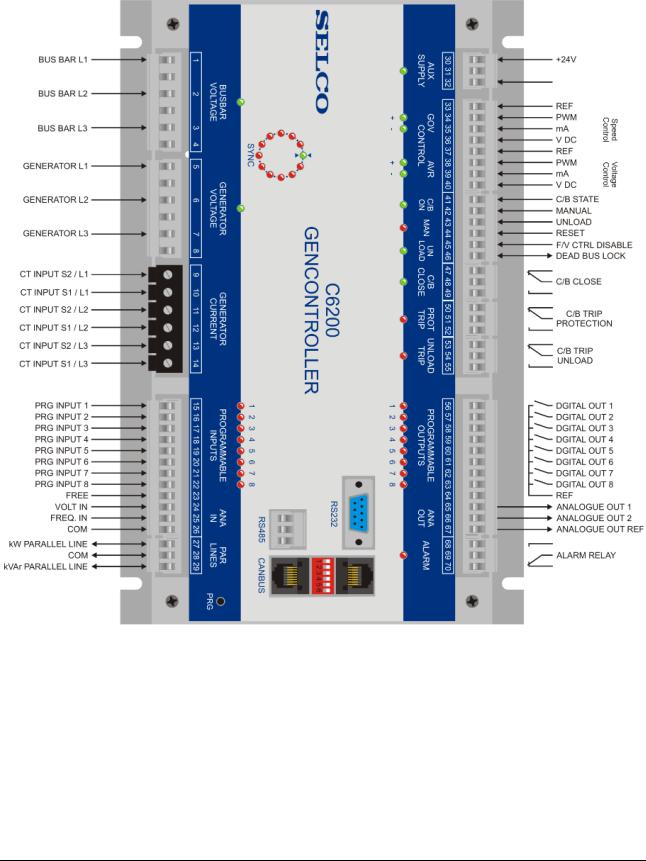
2 Front View
Revision: 11-06-2012 |
Page 4 of 24 |

Littelfuse Selco |
C6200 FlexGen |
|
|
3 Installation
The C6200 FlexGen must be secured to the rear of the switch board using four 5 mm. screws. DIN rail mounting is not advisable due to the weight.
Please ensure that enough space is given around the module so that the plug-in terminals can be removed and reinserted without stressing the wires. The length of the cables should allow for the easy removal and insertion.
Revision: 11-06-2012 |
Page 5 of 24 |

Littelfuse Selco |
C6200 FlexGen |
|
|
4 Isolation and Grounding
In marine installations ground (switchboard chassis) and common reference (COM) should not be connected together. In a marine installation the vessels hull is considered as “ground”.
Connecting any of the COM connections on the C6200 FlexGen to ground (hull) or switchboard chassis may cause electrical noise to be injected into the system.
The general rule is:
COM terminals should not be connected to ground (vessels hull) or to the switchboard chassis.
Negative poles of the power supplies should not be connected to ground (vessels hull) or to the switchboard chassis.
Revision: 11-06-2012 |
Page 6 of 24 |
Littelfuse Selco |
C6200 FlexGen |
|
|
5 Connections
The C6200 FlexGen is wired up through plug-in terminals. The plug-in terminals provide safe and durable connections without sacrificing ease of installation and servicing. One exception is the inputs for the currect transformers, which are fixed terminals to avoid shock from accidental disconnection of live current inputs.
5.1 Power Supply
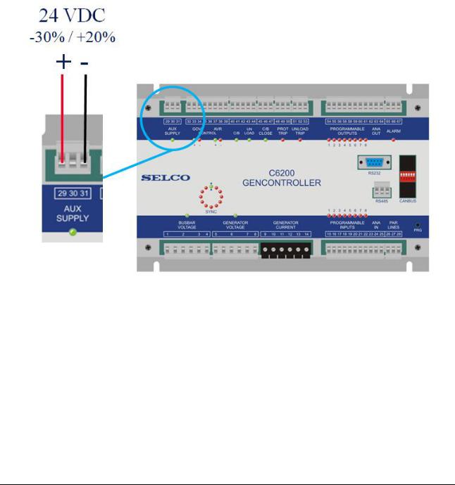
The circuitry of the the C6200 FlexGen must be powered by a single external power supply. The supply must provide a nominal voltage of +24 V DC. The C6200 FlexGen will tolerate relatively wide variations in the supply voltage (please refer to the specifications). The supply is connected to terminal 30 and 32 of the AUX SUPPLY plug-in connector.
Terminal |
Signal |
Description |
30 |
+24 V DC |
Positive terminal of primary supply |
31 |
|
FREE (unused / no connection) |
32 |
-24 V DC |
Negative terminal of primary supply |
The auxiliary power supply is not isolated from the remaining circuitry. This means that the supply reference terminal (terminal 32) has connection to the module’s COM terminal.
The front AUX SUPPLY LED illuminates with a steady green light to indicate that the supply voltage is OK and within the tolerated limits for safe operation.
Revision: 11-06-2012 |
Page 7 of 24 |

Littelfuse Selco |
C6200 FlexGen |
|
|
External switching of the supply (e.g. to power the units on and off) should be done by making or braking positive supply (terminal 30). Do not use terminal 32 to make and break the supply.
5.2 Voltage Inputs
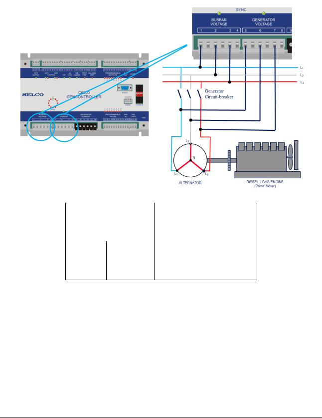
The AC voltages connect to the BUS BAR VOLTAGE and GENERATOR VOLTAGE plug-in terminals.
The voltage inputs can operate with high voltage (up to 690 V AC nominal), so precaution must be taken to avoid electrical shock and personal injury. Do not touch the voltage input plug-in terminal unless you are absolutely sure that both the busbar and generator is off. The generator should be stopped and blocked against starting – the busbar should be dead. Also make sure that there is no risk of another power source being connected to the busbar while you are working with the voltage inputs.
Voltages above 690 V AC are supported through use of external transformers (PT). When using PTs please ensure that the PT does not affect the phase of the AC voltage measurement. Phase shift in the PT will directly affect the calculation of power factor, and thereby the calculation of active and reactive currents and loads.
The phases L1, L2 and L3 of the busbar and generator voltage must be connected to L1, L2 and L3 of the busbar/generator voltage input plug-in terminals. Intermediate 2 A slow-blow fuses should be inserted between the individual phases and the related voltage inputs.
Revision: 11-06-2012 |
Page 8 of 24 |
Littelfuse Selco |
C6200 FlexGen |
|
|
It is important that the phases are connected in the correct order (correct phase sequence). Interchanging the phases will result in an incorrect power factor calculation and thereby incorrect calculation of active/reactive currents and loads. It is important that the phases are connected to the corresponding terminals (phase 1 to L1, phase 2 to L2 and phase 3 to L3).
Terminal |
Signal |
Description |
1 |
AC voltage |
Bus bar phase L1 |
2 |
AC voltage |
Bus bar phase L2 |
3 |
AC voltage |
Bus bar phase L3 |
Terminal |
Signal |
Description |
5 |
AC voltage |
Generator phase L1 |
6 |
AC voltage |
Generator phase L2 |
7 |
AC voltage |
Generator phase L3 |
The BUSBAR VOLTAGE LED shows (by steady light) whether the voltage levels measured between the phases are within limits. The reference is the nominal phase-phase voltage (NOMVOLT) that has been entered in the configuration. The toleance is defined by the voltage OK window (VOLTOKWND) also present in the configuration.
The same scheme applies to the GENERATOR VOLTAGE LED. However, on older versions of the C6200 FlexGen the LED will also flash while the generator breaker is open. This depends on the firmware revision.
Revision: 11-06-2012 |
Page 9 of 24 |
Littelfuse Selco |
C6200 FlexGen |
|
|
5.3 Current Inputs
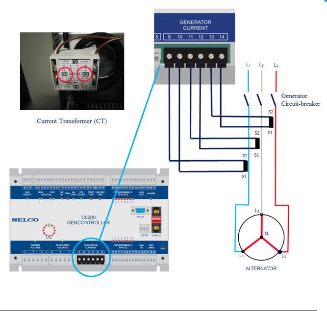
The V6200 FlexGen measures current through external current transformers (CTs). The C6200 FlexGen supports both 1 A and 5 A CTs. Class 1 CTs for protection is recommended. The CTs can be shared with third-party equipment provided that this equipmed due not place a burden on the CTs (that the CT inputs are isolated by e.g. transformers inside the third-party equipment).
The CT ratio should cover the maximum current of the generator.
The CTs must be capable of coping with limited time short-circuit currents without going into saturation (Protection Transformers).
The external CTs connect to the GENERATOR CURRENT terminals. It is important to ensure that the direction of the current flow is correct. The current flow is usually indicated by S1 and S2 notations on the CT enclosure. S1 of the CT on phase 1 connects to terminal 10 and S2 connects to terminal 19. Likewise with the CTs of phase 2 and 3.
Revision: 11-06-2012 |
Page 10 of 24 |