

C6200 FlexGen
.pdfLittelfuse Selco |
C6200 FlexGen |
|
|
Terminal |
Signal |
Description |
65 |
DC voltage |
External voltage input |
66 |
DC voltage |
External voltage input |
67 |
Reference (COM) |
Internal reference |
It is important to note that each analogue output is protected against short-circuit by an internal 10 kΩ resistor. Resistors are placed in series on the output terminal. The output resistor might affect the magnitude of the output signal if the internal resistance of the driven equipment is low. The principle of voltage division applies between the output resistor and the internal resistance of the driven equipment. Example: equipment with an internal resistance of only 10 kΩ would reduce a +10 VDC output voltage to +5 VDC. The two 10 kΩ resistors in series would make a 1:2 voltage divider.
5.12 Alarm
The alarm relay includes two contact sets. The alarm relays can only operate as normally energized relays. This is to ensure that the alarm relay will trip in case the supplies fail.
The alarm relay can also be configured to trip on a protection fault.
Terminal |
Description |
Signal |
Connection |
68 |
Alarm Contact |
Relay de-energized position |
Alarm system |
69 |
Alarm Contact |
Relay contact |
Signal source |
70 |
Alarm Contact |
Relay energized position |
Alarm system |
Revision: 11-06-2012 |
Page 21 of 24 |
Littelfuse Selco |
C6200 FlexGen |
|
|
5.13 RS485
The C6200 FlexGen module includes an isolated RS485 interface.
Terminal |
Description |
Signal |
Connection |
Left |
B - |
RS485 B |
B signal of the RS485 bus |
Middle |
A + |
RS485 A |
A signal of the RS485 bus |
Right |
REF |
Reference (isolated) |
Reference of the RS485 bus |
It is important to note that the RS485 reference is isolated from the common COM of the module.
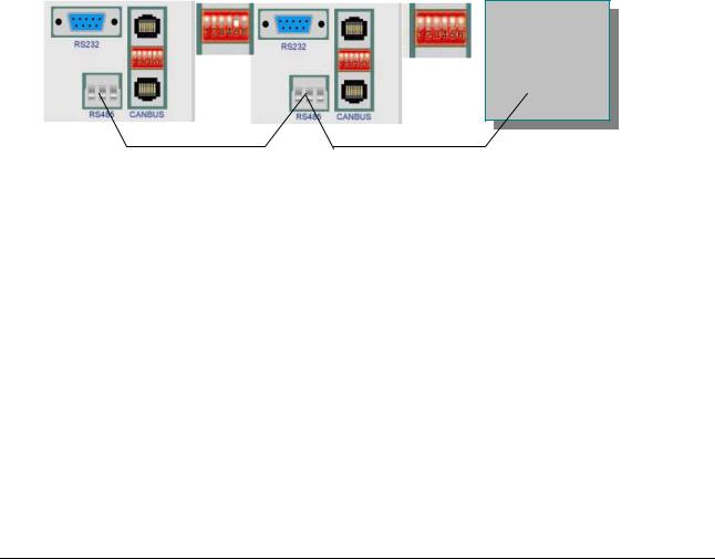
The 3-wire RS485 bus is connected from module to module.
A RS485 bus needs termination resistance (150 Ω) between terminals A and B at end end of the cable. It is not necessary to connect external termination resistors as the C6200 FlexGen contains internal resistors that can be enabled by toggeling DIP switch 5 to ON position. The termination resistor must be enabled only on the first and on the last unit on the RS485 bus.
The maximum cable length for RS485 is 1.000 meters. The cable must be twisted pair (A and B twisted inside the cable). The cable should be shielded. One end of the shield (and only one end) nust be connected to switchboard chassis.
Cable 2-LiYCY TP shielded 2x2x0,75 can be used
PLC
It is sometimes necessary to fix the potential of the RS485 + and – lines due to interference from other sources. This is done with two 1 kΩ resistors using a technique called “Biasing”. One resistor is fixed between RS485 A and an external +5 V DC supply, the other is fixed between RS485 B and the reference of the +5 V DC supply. The reference of the 24 VDC (terminal 32) supply must then be connected to rightmost terminal of the RS485 plug on each and every module.
Revision: 11-06-2012 |
Page 22 of 24 |
Littelfuse Selco |
C6200 FlexGen |
|
|
5.14 CAN bus
The CAN bus is used in connection with the load dending start/stop features of the C6200 FlexGen.
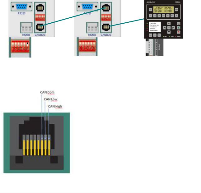
The CANbus terminals are located on the front plate in the right side. The terminals are module standard used in Data communication equipment. Therefore, use standard twisted pair patch cable for CANbus wiring. The maximum cable length is 40 meters. The cable type should be 0.25 - 0.34 mm2 (AWG23/AWG22). Cable resistance should be less than 26 mΩ per meter.
The first and the last module on the CANbus need a termination resistor (150 Ω) between lines A and B. It is not necessary to connect external resistors. The C6200 FlexGen contains internal end of line resistors for the CAN bus that can be activated by toggeling DIP switch 6 to ON position. Therefore, on the first and on the last unit on the CAN bus, DIP switch 6 has to ON. Every C6200 FlexGen module must be connected to the same CAN bus network. Third party CAN nodes may not be connected to the FLEXGEN CAN bus.
|
|
|
|
150Ω resistor |
150Ω resistor |
||
via dip switch |
|
|
|
RJ45 Connector for CAN bus:
Revision: 11-06-2012 |
Page 23 of 24 |

Littelfuse Selco |
C6200 FlexGen |
|
|
6 Specifications:
Voltage supply |
: |
10 VDC to 36 VDC (24VDC -58% / +50%) |
Generator Voltage |
|
63V to 690V |
Generator rated frequency |
|
50Hz/ 60Hz |
Generator max current |
|
30.000A |
Current transformer secondary current |
5A |
|
Power Consumption |
|
7W |
Ambient temp range |
|
-20 ºC / +70 ºC |
Vibration: |
|
IEC 60068-2-6 |
Humidity: |
|
IEC 60068-2-30 |
EMC: |
|
IEC 61000-4-3:2006, IEC 61000-4-6:2004, IEC 61000-4- |
|
|
5:2005, IACS E10:2006 Test No.15, CISPR 16-1:1999, |
|
|
CISPR 16-2:2002 |
Relay contacts |
|
230VAC / 2A & 30VDC / 2A |
External communication |
|
MODBUS RTU |
Programmable digital inputs |
8 |
|
Programmable digital outputs |
8 |
|
Programmable analogue outputs |
2 |
|
Current measurement |
|
3 phase |
Enclosure: |
|
IP20 |
Weight |
|
1,5 Kg |
Dimension (mm) |
|
(282 x 182 x 50)mm |
Revision: 11-06-2012 |
Page 24 of 24 |