

C6200 FlexGen
.pdfLittelfuse Selco |
|
|
C6200 FlexGen |
|
|
|
|
|
|
|
|
|
|
|
|
Terminal |
Signal |
Description |
|
|
9 |
AC current |
S2 of the CT on phase L1 |
|
|
10 |
AC current |
S1 of the CT on phase L1 |
|
|
11 |
AC current |
S2 of the CT on phase L2 |
|
|
12 |
AC current |
S1 of the CT on phase L2 |
|
|
13 |
AC current |
S2 of the CT on phase L3 |
|
|
14 |
AC current |
S1 of the CT on phase L3 |
|
Make sure that the secondary side of the CT is shorted (make a connection between S1 and S2) before you disconnect the CT cables from the GENERATOR CURRENT terminals.
Please note that incorrect connection of the current transformers (e.g. by reversing the terminals S1 and S2) will result in wrong current, power and power factor readings.
Correct measurement of the current is extremely important. The C6200 FlexGen relies upon the current measurements for the calculation of power factors, active currents and loads, reactive currents and loads, integrated protection functions and load sharing.
Connection of bus & generator voltages and currents
Revision: 11-06-2012 |
Page 11 of 24 |

Littelfuse Selco |
C6200 FlexGen |
|
|
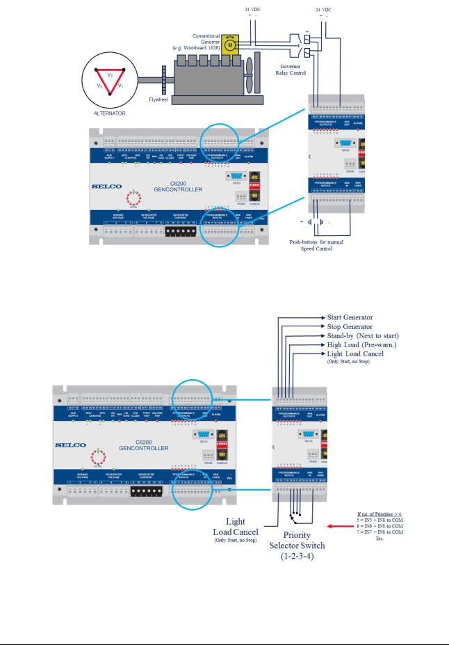
5.4 Programmable Inputs
The programmable input connector provides a number of digital inputs. The digital inputs work with negative reference (COM), meaning the inputs are considered active when they are connected to minus supply, and inactive when left open (disconnected). The inputs are used for external activations of various programmable features. The functions are described in the C6200 FlexGen Configuration Manual.
Terminal |
Signal |
Description |
15 |
NO contact to COM |
Programmable input 1 |
16 |
NO contact to COM |
Programmable input 2 |
17 |
NO contact to COM |
Programmable input 3 |
18 |
NO contact to COM |
Programmable input 4 |
19 |
NO contact to COM |
Programmable input 5 |
20 |
NO contact to COM |
Programmable input 6 |
21 |
NO contact to COM |
Programmable input 7 |
22 |
NO contact to COM |
Programmable input 8 |
23 |
FREE |
|
Example for connection of a digital input:
The figures on the next page show the programmable inputs and outputs being used for control of a conventional speed governor (with increase descrase relay pulses) and for load depending start and stop.
Revision: 11-06-2012 |
Page 12 of 24 |
Littelfuse Selco |
C6200 FlexGen |
|
|
Programmable inputs and outputs used for control of conventional speed governor.
Programmable inputs and outputs used for load depending start and stop.
Revision: 11-06-2012 Page 13 of 24

Littelfuse Selco |
C6200 FlexGen |
|
|
5.5 Analogue Inputs
The analogue inputs are used for external control of voltage, frequency and load. For example, the analogue inputs can be used when two busbar sections are to be synchronized together or when the gerator is to be synchronized to an incoming sharft generator (or the grid). The analogue inputs can also be used in case the load of the generator needs to be remotely controlled e.g. in grid paralleling application.
5.5.1Voltage Input
The voltage input (terminal 24) is an analogue input. The input can be used for external control of the generator voltage, provided that the F/V CTRL. DISABLE input has been activated (connected to COM) or a grid parallel operation scheme is activated. The analogue control signal must be a voltage between 0 and +5 V DC. The voltage input uses the COM terminal as reference. When not used its is recommended that the voltage input is connected to COM. This is especially important if the F/V CTRL. DISABLE input is made active while no signal is provided to the voltage input.
Terminal |
Signal |
Description |
24 |
0 to +5 V DC |
Remote Voltage Control |
26 |
COM |
Common reference |
Please note that terminal 26 (COM) is internally connected to terminal 32 (Supply minus). In rare situations “gound loops” can cause noise to be injected into the application. Ground loops happen when multiple COM connections between modules (e.g. parallel operating C6200 units) exist. Ground loops can be avoid by only using terminal 32 as the common connection point for all COM connections.
5.5.2Frequency Input
Like thr voltage input, the frequency input is an analogue input. The input can be used for external control of the generator frequency, provided that the F/V CTRL. DISABLE input is active (connected to COM) or a grid parallel operation scheme is activated. The analogue control signal must be a voltage between 0 and +5 V DC. The frequency input uses the COM terminal as reference. When not used its is recommended that the frequency input is connected to COM. This is especially important if the F/V CTRL. DISABLE input is made active while no signal is provided to the frequency input.
Terminal |
Signal |
Description |
25 |
0 to +5 V DC |
Remote Frequency Control |
26 |
COM |
Common reference |
Please note that terminal 26 (COM) is internally connected to terminal 32 (Supply minus). In rare situations “gound loops” can cause noise to be injected into the application. Ground loops happen when multiple COM connections between modules (e.g. parallel operating C6200 units) exist. Ground loops can be avoid by only using terminal 32 as the common connection point for all COM connections.
Revision: 11-06-2012 |
Page 14 of 24 |
Littelfuse Selco |
C6200 FlexGen |
|
|
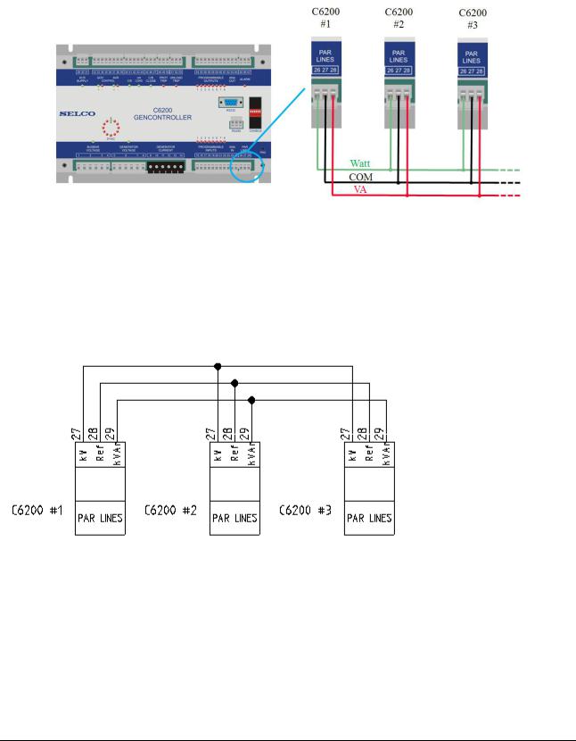
5.6 Parallel Lines
The parallel lines are used for balancing the active and reactive currents/loads between parallel running C6200 FlexGen modules. The signal level of the parallel lines can also be adapted to suit other types of Littelfuse Selco load sharers (e.g. the Littelfuse Selco T4800).
Terminal |
Signal |
Description |
27 |
DC voltage |
kW BALANCE of other FLEXGEN |
|
|
modules |
28 |
Common reference |
COM of the other FLEXGEN modules |
29 |
DC voltage |
kVAr BALANCE of other FLEXGEN |
|
|
modules |
Please note that terminal 28 (COM) is internally connected to terminal 32 (Supply minus). In rare situations “gound loops” can cause noise to be injected into the application. Ground loops happen when multiple COM connections between modules (e.g. parallel operating C6200 units) exist. Ground loops can be avoid by only using terminal 32 as the common connection point for all COM connections.
Revision: 11-06-2012 |
Page 15 of 24 |

Littelfuse Selco |
C6200 FlexGen |
|
|
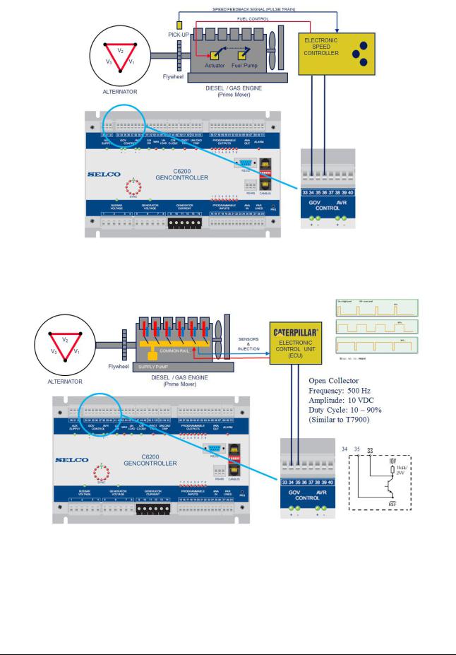
5.7 GOV/AVR Control
Two sets of analogue outputs are provided for the control of speed and voltage. The analogue outputs are intended for direct control of electronic speed governors and AVRs. Each analogue output can be configured to provide either a DC voltage within the range of -10 to +10 V DC, a DC current within the range of 0 to 20 mA or a PWM signal with a default base frequency of 500 Hz.
The analogue outputs are isolated from each other and from the remaining circuitry. This means that the references of the outputs have no connection to each other or to the common reference (COM).
Terminal |
Signal |
Connection |
33 |
reference (isolated) |
Governor reference |
34 |
PWM signal |
Governor PWM input |
35 |
DC current |
Governor current input |
36 |
DC voltage |
Governor voltage input |
37 |
reference (isolated) |
AVR reference |
38 |
PWM signal |
AVR PWM input |
39 |
DC current |
AVR current input |
40 |
DC voltage |
AVR voltage input |
It is important to note that each analogue output is protected against short circuit by an internal 10 kΩ resistor. The resistor is located inside the C6200 and placed in series with the output. The output resistor might affect the magnitude of the output signal if the internal resistance of the external equipment (e.g. the aux speed input of the governor) is low. The principle of voltage division applies between the output resistor and the internal resistance of the external equipment. Most governors and AVRs have high impedeance inputs, so the 10 kΩ resistance will typically not be an issue.
Example: A governor with aux speed input having an internal resistance of only 10 kΩ would reduce a +10 VDC output voltage to +5 VDC. The two 10 kΩ resistors in series would make a 1:2 voltage divider.
Revision: 11-06-2012 |
Page 16 of 24 |
Littelfuse Selco |
C6200 FlexGen |
|
|
C6200 FlexGen controlling electronic speed governor by a DC voltage.
C6200 FlexGen controlling ECU by a PWM signal.
Note that the amplitude of the PWM signal is determined by the configuration of the DC voltage output range (e.g. 0 to 10 V DC).
Revision: 11-06-2012 |
Page 17 of 24 |

Littelfuse Selco |
C6200 FlexGen |
|
|
5.8 Inputs
The inputs plug-in connector houses a number of general purpose inputs. The inputs work with negative reference, meaning that the inputs are considered active when connected to negative supply and inactive when disconnected.
Terminal |
Signal |
Description |
41 |
C/B |
External switch, output or relay |
42 |
Manual |
External switch, output or relay |
43 |
Unload |
External switch, output or relay |
44 |
Reset |
External switch, output or relay |
45 |
F/V Ctrl Disable |
External switch, output or relay |
46 |
Dead Bus Lock |
To be interconnected with the Dead Bus Lock terminals of each |
|
|
C6200 FlexGen module in the system |
5.8.1C/B
The C/B input provides feedback from the generator circuit breaker and is used to determine wether the breaker is open or closed. C/B is typically connected to COM through an auxiliary contact of the breaker. The breaker is considered closed when the C/B input is at COM level.
Please note that the C/B input is very important to the function of the C6200 FlexGen. The C/B input is used (together with the state af the voltage inputs) to determine the operational situation of the system.
5.8.2Manual
Activating the manual input will prevent the C6200 FlexGen from interfering with the speed and voltage controls of the generator, unless it gets a command to do so via the programmable inputs (terminals 15 to 22). The manual input is active when at COM level and inactive if left disconnected.
5.8.3Unload
The UNLOAD input is used to initiate a controlled unload of the generator whereafter the C6200 FlexGen will issue a trip signal to the breaker. Unload starts when the signal is put to COM level. Disconnecting the unload signal during operation will causes reload and/or reconnection of the generator.
5.8.4Reset
Reset Alarm is used to reset the alarm relay. Reset Alarm is active when the input is at COM level.
5.8.5F/V Ctrl. Disable
The F/V CTRL. DISABLE input is used to deactivate the voltage and frequency stabilization. This input is considered active when the input is connected to COM level, and inactive when disconnected. The signal is typically used when the generator is operated in parallel with a shaft generator or the grid (power sources that determine the voltage and frequency). Other applications are where the voltage and frequency is controlled by third-party equipment (through the voltage and frequency analogue inputs on terminals 25 and 26).
Revision: 11-06-2012 |
Page 18 of 24 |
Littelfuse Selco |
C6200 FlexGen |
|
|
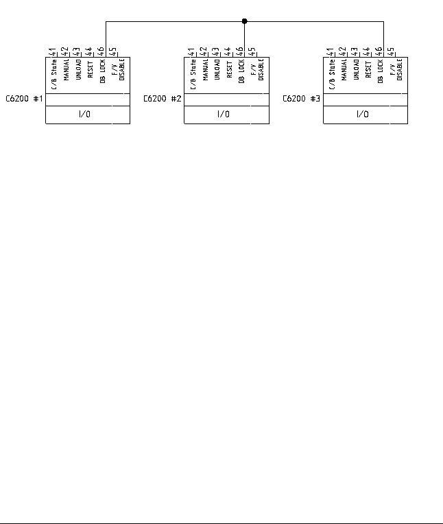
5.8.6Dead Bus lock
The dead bus lock signal is used to prevent more than one generator from connect simultaneously to a dead bus bar (e.g. in a blackout situation).
The Dead Bus Lock signal (terminal 46) must be interconnected between all C6200 FlexGen modules that operates generator connecting to the same busbar.
Wiring of Dead bus Lock signal
5.9 Relays
5.9.1C/B Close
The C/B close relay is a change-over relay intended for control (Closure) of the generator circuit breaker. The C/B close relay has two contact sets and is normally de-energized by default. Note that this relay can be reconfigured to normally energized operation.
Terminal |
Signal |
Description |
47 |
Relay de-energized position |
Breaker remote close |
48 |
Relay contact |
Signal source |
49 |
Relay energized position |
Breaker remote close |
5.9.2Protection Trip
The protection trip relay is a change-over relay intended for tripping the circuit breaker in case of a protection fault (e.g. over-curremt or reverse power). The built-in protection trip relay has two contact sets and is normally energized by default. Note that the protection trip relay can be reconfigured to normally energized operation.
Terminal |
Signal |
Description |
50 |
Relay de-energized position |
Breaker remote trip |
51 |
Relay contact |
Signal source |
52 |
Relay energized position |
Breaker remote trip |
The protection trip relay connects to the remote trip input of the generator circuit breaker. Terminals 50 and 52 are typically not connected at the same time. Only one of these signals is taken to the breaker, depending on whether the Protection Trip relay is configured for normally energized or de-energized operation.
Revision: 11-06-2012 |
Page 19 of 24 |
Littelfuse Selco |
C6200 FlexGen |
|
|
5.9.3Unload Trip
The unload trip relay connects to the remote trip input of the generator circuit breaker. Terminals 52 and 55 are typically not connected at the same time. Only one of these signals is taken to the breaker, depending on whether the unload trip relay is configured for normally energized or deenergized operation. The unload trip relay disconnects the circuit breaker after the generator has been unloaded by the unload function.
Terminal |
Signal |
Description |
53 |
Relay de-energized position |
Breaker remote trip |
54 |
Relay contact |
Signal source |
55 |
Relay energized position |
Breaker remote trip |
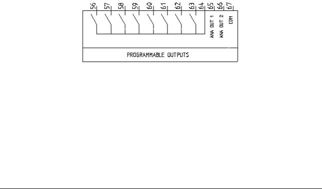
5.10 Programmable Outputs
The programmable outputs are potential free relay outputs (Normally opened). The common reference of all programmable outputs is terminal 64 (REF). The outputs are used for indication and control of external equipments (e.g. common alarms or speed/voltage control relay pulses).
Terminal |
Signal |
Description |
56 |
Normally open relay output |
Programmable output 1 |
57 |
Normally open relay output |
Programmable output 2 |
58 |
Normally open relay output |
Programmable output 3 |
59 |
Normally open relay output |
Programmable output 4 |
60 |
Normally open relay output |
Programmable output 5 |
61 |
Normally open relay output |
Programmable output 6 |
62 |
Normally open relay output |
Programmable output 7 |
63 |
Normally open relay output |
Programmable output 8 |
64 |
COM |
Reference |
5.11 Analogue Outputs
The analogue outputs are intended for use with analogue meters or external indication equipment. Each of the two outputs can be individually configured in relation to any one of the measured or calculated parameters provided within the C6200 FlexGen.
Each analogue output can be configured to provide a DC voltage within the range of -10 to +10 V DC. The two outputs both uses COM as reference.
Revision: 11-06-2012 |
Page 20 of 24 |