

1 Synchronous-motor-rotor pole
Principle of operation. Basically, the synchronous-motor operation depends on the force produced by a current-carrying conductor lying within a magnetic field. The force, acting at some distance from an axis, produces a torque, which may then produce rotation. In the synchronous motor, the conductor is stationary and the torque causes rotation of the field. In Fig.2 using the conventional right-hand rule, the force on the conductor is to the right. Since the conductor is stationary and the field is on the shaft, motion is produced in a counter-clockwise direction. When the current in the conductor is reversed, the force on it will also reverse, and the rotor will tend to move in a clockwise direction, provided that the conductor is still within the field of the north pole. When starting from the rest, this is substantially true since reversal of the current occurs much more rapidly than movement of the rotor. If, therefore, both rotor and stator are simultaneously energized from rest, there is no starting torque.
On the other hand, if the rotor is already moving at synchronous speed, the rotor will move through 180 electrical degrees during the one half cycle that the current in the conductor takes to reverse. This means that after one half cycle, a pole of opposite polarity is now opposite the same conductor whose current has reversed. With a reversal of both current and magnetic field, force on the conductor remains in the same direction. This is shown in Fig.3.
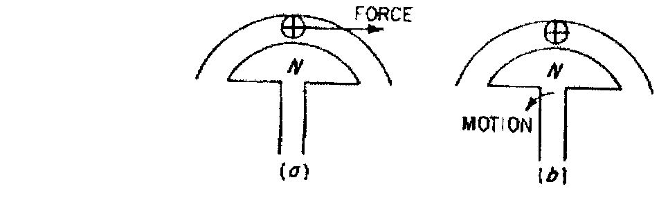
Fig.2 Motion of synchronous-motor rotor
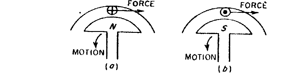
Fig.3 Rotor motion with reversal of armature current
In order to maintain rotation, the current in the conductor must go through one half cycle in the same time that the field rotates one pole pitch. For a two pole motor, this half cycle must occur for a rotation of 180° in space; for a four-pole motor, it must occur for a rotation of 90° in space; and so on. We see therefore, that the speed of the rotor, i.e., synchronous speed, is determined by the same factors as is synchronous speed of an induction motor, namely, the supply frequency and the number of poles. The synchronous-motor principle may be viewed in a somewhat different manner. Since the armature is wound like that of an alternator, and hence a polyphase-induction-motor stator, a three-phase stator supply produces a uniform rotating field. With both rotor and stator energized, the motor may be viewed in the manner shown in Fig.4.
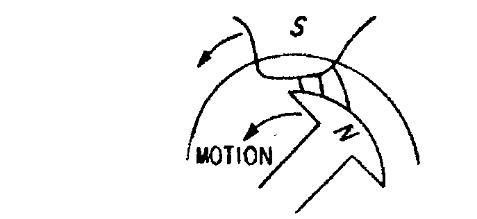
Fig. 4 Stator and rotor fields
The stator field is assumed to have a sinusoidal distribution. This field, in the position shown, attracts the rotor and will continue to pull it around at synchronous speed. If, however, the rotor starts from rest, in one half cycle, a stator north pole will be opposite the rotor north pole, and before the rotor can move any appreciable distance in the direction of the stator field, there will be a repelling force. It is thus again seen that with both stator and rotor simultaneously energized from rest, the starting torque is zero.
Methods of starting a synchronous motor. If both rotor and stator are excited, the synchronous motor develops no torque at standstill. It will, however, develop running torque once it has been brought up to synchronous speed and then properly excited. There are several methods of accomplishing this.
Auxiliary drive. A directly coupled induction motor can be used. If the induction motor has a rating of about 10 per cent of that of the synchronous motor, it is usually sufficient to bring the rotor up to speed without load. The auxiliary induction motor should have two poles fewer than the synchronous motor, so that, allowing for slip, the speed attained after starting is above the synchronous speed of the main motor, since the same polyphase supply is used for both. The dc field is then applied so that there is a generated voltage in the armature. If the power supply to the induction motor is now removed, both motors slow down and the induced armature frequency approaches line frequency. The synchronous motor, now operating as a generator, can be synchronized with the supply lines, and it will continue to rotate at synchronous speed within its load rating.
The same auxiliary-drive method may be used even without the synchronizing procedure. It is merely necessary to measure speed and to make certain that the stator fields on both the induction and synchronous motors rotate in the same direction.
The auxiliary motor need not be an induction motor. Where a dc exciter is coupled to the motor shaft and a separate dc supply is also available, the exciter may be driven as a shunt motor, bringing the synchronous motor up to speed as before. If the load of the synchronous motor happens to be a dc generator, it too may be operated as a shunt motor in order to start the synchronous motor.
Induction start. The squirrel-cage winding embedded in the pole faces develops torque when a three-phase supply is connected across the armature terminals and sets up a rotating field in the stator. In larger machines, across-the-line starting causes a great initial current inrush, and so reduced voltage starting is often used. The field-pole winding, which has a relatively large number of turns, is also cut by the revolving stator field and may have a dangerously high voltage induced on it. One method to prevent this high voltage is to use a field –sectionalizing, or breakup, switch which divides the field winding into sections so that the voltages induced are not cumulative. Another preventive method is to short-circuit the field on itself or close it through an external resistor, thereby providing an IR drop in either case.
After the rotor is accelerated to its constant induction motor speed, the stator field is moving rather slowly relative to the rotor field. Because of magnetic induction, each field pole becomes alternately polarized at slip speed. The effect of hysteresis may, at some point, magnetize each pole in only one direction. This is especially true in a salient-pole machine, since the presence of air gaps between adjacent poles tends to maintain the flux in the iron as shown in Fig. 5 and thus induce polarities in the rotor poles as shown.
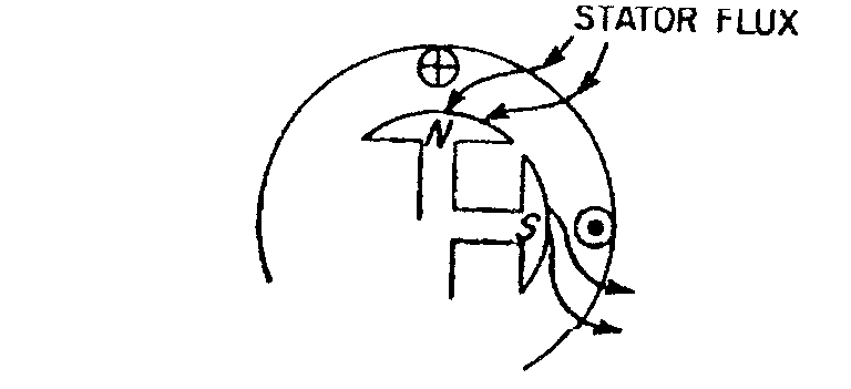
Fig 5 Magnetizing of rotor poles
Even without direct current applied to the field winding, the motor now has the requisites of a synchronous motor, and sufficient torque may be developed to bring the rotor up to synchronous speed.