

LABORATORY WORK 4
MEASURING OF CURRENTS, VOLTAGES AND PARAMETERS OF ELECTRIC CIRCUITS BY COMBINED DEVICES (TESTERS)
The purpose of the work: to study action principle, building and features of the combined devices (CD), to acquire habit in measuring and testing of electric circuit elements by means of CD.
Preparation for the work processing requires:
Study the manual of the given work and the appropriate sections of the recommended literature [2,3,4].
To be able to answer the following questions:
What is the purpose of this work?
What can be measured and tested by means of CD?
What action principle, building, advantages and disadvantages a meter movement of CD has?
What is the difference between schemes and scales of ohmmeter and kiloohmeter?
How can a resistor be connected to CD to use the ‘Ω’ and ‘MΩ’ scales?
How does ammeter scheme of the full-scale range change act? What are peculiarities and advantages of universal shunt?
What are the reasons of CD temperature error and how is it compensated?
How does voltmeter scheme of the full-scale range vary?
Why and how CD frequency band is limited? What schemes of frequency compensation do you know?
What schemes have half-and- full-wave rectifier voltmeters?
Why is half-wave scheme used for measuring of small voltages?
ЛАБОРАТОРНА РОБОТА 4
ВИМІРЮВАННЯ СТРУМІВ, НАПРУГ ТА ПАРАМЕТРІВ ЕЛЕКТРИЧНИХ ЛАНЦЮГІВ КОМБІНОВАНИМИ ПРИЛАДАМИ (ТЕСТЕРАМИ)
Мета роботи: вивчити принцип дії, будову та властивості комбінованих приладів (КП), здобути навички вимірювань і перевірки справності елементів електричних ланцюгів із допомогою КП.
При підготовці до виконання роботи необхідно:
1) Опрацювати опис цієї роботи та відповідні розділи рекомендованої літератури [2, 3, 5].
2) Уміти відповідати на наступні запитання:
1 Яка мета цієї роботи?
2. Що можна вимірювати та перевіряти за допомогою КП?
3. Який принцип дії, будову, переваги та недоліки має вимірювальний механізм КП?
4. В чому відмінність схем і шкал омметра та кілоомметра?
5. Як приєднувати до КП досліджуваний резистор, щоб користуватися шкалами “Ω“ та “МΩ“?
6. Як діє схема зміни межі вимірювання амперметра? В чому особливості та переваги універсального шунта?
7. Які причини температурної похибки КП і як вона компенсується?
8. Як змінюються межі вимірювання вольтметра?
9. Чому і наскільки обмежений частотний діапазон КП? Які схеми частотної компенсації Вам відомі?
10. Які схеми мають одно – та двопівперіодний випрямний вольтметри?
11. Чому для вимірювання малих напруг використовують однопівперіодну схему?
What is the function of the second diode in the half-wave scheme?
What a.c. voltage does CD indicate at operating range of 250V, at pointer position shown on fig.4.6? What absolute and relative errors of measurement are allowable?
What resistance is indicated by CD at the operating range of kΩ x 10, at the pointer position shown on fig.4.6? How the permissible absolute and relative errors of measurement for this indication may be defined?
How the diode and transistor’s sanity can be checked by means of CD?
How the condenser and transformer’s sanity can be tested by means of CD?
Why CD can measure only the sinusoidal alternating currents and voltages?
Brief theoretical information
Multirange combined electromeasuring instruments are used for measuring of currents and voltages in direct and sinusoidal alternating currents circuits, as well as a resistance, capacity, relative voltage level etc.
In this laboratory work only portable multirange CD for measuring of direct and sinusoidal alternating currents and voltages, and also a resistance of direct current is considered. Users of these devices, in practice, mostly call them testers (from English – to test), sometimes they call them volt-ammeters, or avometer. The deflect meter movement (MM) of the enough high sensibility – permanent magnet
12. Яке призначення другого діода в однопівперіодній схемі?
13. Яку напругу змінного струму показує на межі 250V КП при положенні стрілки, вказаному на рис.4.6? Яка при цьому допускається абсолютна та відносна похибка вимірювання?
14. Який опір показує КП на межі кΩ х 10 при положенні стрілки, вказаному на рис.4.6? Як визначити для цього показу допустиму абсолютну та відносну похибки вимірювання?
15. Як за допомогою КП перевірити справність діода та транзистора?
16.Як за допомогою КП перевірити справність конденсатора та трансформатора?
17. Чому КП може вимірювати тільки синусоїдальні змінні струми та напруги?
Короткі теоретичні відомості
Багатограничні комбіновані електровимірювальні прилади призначені для вимірювання струмів і напруг у мережах постійного та синусоїдального змінного струмів, а також опору змінному струмові, ємності, відносного рівня напруги і т.ін.
У цій лабораторній роботі розглянуті тільки переносні багатограничні КП для вимірювання постійних і змінних синусоїдальних струмів і напруг, а також опору постійному струмові.
У практиці користувачів цих приладів їх найчастіше називають тестерами (від англійського test – випробовувати), іноді – ампервольтомметрами, авометрами.
Основним вузлом КП є стрілковий вимірювальний механізм (ВМ) досить високої чутливості – магнітоелектричний
microammmeter with full-scale current of (50..100) μA is a basic CD unit.
Selection namely of permanent magnet MM as CD base unit is specified by its important advantages:
by high sensibility (due to strong magnetic field of permanent magnet it is enough to have small current for creation of necessary actuating torque);
by high accuracy (due to MM details parameters stability, their independence from electric and small influence of magnetic fields, and also presence of enough simple and effective methods of temperature errors compensation);
by linear scale;
by small power draw from object power (only units, or even parts of milliwatts) that stipulates small device influence on object.
As for deficiencies of permanent magnet MM, that is relatively complicated construction and inaptitude for direct measuring of alternating currents and voltages. A first deficiency is easily corrected by modern instruments-making industry, and second deficiency is easily corrected by application of different measuring transducers (for example, semiconductor diodes), which rectify a measured alternating current or voltage in front of supply to MM.
Permanent magnet MM, under its connection in series with object, can measure only a small current, and under its connection in parallel to
мікроамперметр зі струмом повного відхилення (50...100) μА.
Обрання саме магнітоелектричного ВМ основою КП зумовлено його суттєвими перевагами:
- високою чутливістю (завдяки сильному магнітному полю постійного магніта достатньо малого струму для створення потрібного обертального момента);
- високою точністю (завдяки стабільності параметрів елементів ВМ, їх незалежності від електричних і малому впливові магнітних полів, а також наявності досить простих і ефективних засобів компенсації температурних похибок);
- рівномірною шкалою;
- малою споживаною від об'єкта потужністю (лише одиниці, або навіть частки міліват),що зумовлює малий вплив приладу на об'єкт.
Щодо недоліків магнітоелектричного ВМ, то це відносно складна конструкція та непридатність для безпосереднього вимірювання змінних струмів і напруг. Перший недолік легко долається сучасною приладобудівною промисловістю, а другий-застосуванням різних вимірювальних перетворювачів (наприклад, напівпровідникових діодів), які спрямляють вимірюваний змінний струм або напругу перед подачею на ВМ.
Сам магнітоелектричний ВМ, при його з'єднанні послідовно з об'єктом, може вимірювати лише невеликий струм, а при приєднанні паралельно
object can measure small voltage, but still with an appreciable temperatures errors, firstly specified by resistance dependence of its cupreous moving coil on temperature. That is why in practical CD schemes it uses necessarily with measuring chain, appointed for compensation of temperature error (R11, R12) and with universal shunt resistance for measured currents operating ranges (R1…R8) switching by fig. 4.1 or multiplier resistors for voltage operating range (R9…R21) switching by fig.4.2.
Fig.4.1 Scheme of measured current operating range by universal shunt switching

Fig.4.2 Scheme of measured voltage operating range change by switching of multiplier resistors
о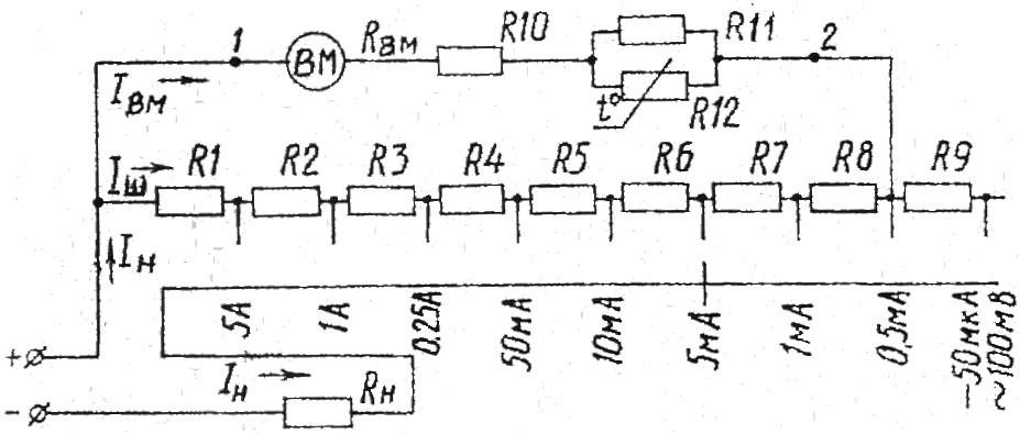 б'єктові
- малу напругу, та ще й з помітними
температурними похибками, зумовленими,
перш за все, залежністю опору його мідної
рухомої котушки (рамки) від температури.
Тому в практичних схемах КП він
застосовується обов'язково з вимірювальним
ланцюгом, призначеним для компенсації
температурної похибки (R11,
R12) та резисторами
універсального шунта для перемикання
меж вимірюваних струмів (R1...R8)
рис.4.1 або додатковими резисторами для
перемикання меж вимірювання напруги
(R9...R21) -
рис.4.2.
б'єктові
- малу напругу, та ще й з помітними
температурними похибками, зумовленими,
перш за все, залежністю опору його мідної
рухомої котушки (рамки) від температури.
Тому в практичних схемах КП він
застосовується обов'язково з вимірювальним
ланцюгом, призначеним для компенсації
температурної похибки (R11,
R12) та резисторами
універсального шунта для перемикання
меж вимірюваних струмів (R1...R8)
рис.4.1 або додатковими резисторами для
перемикання меж вимірювання напруги
(R9...R21) -
рис.4.2.
Рис. 4.1.Схема зміни межі вимірюваного струму перемиканням універсального шунта
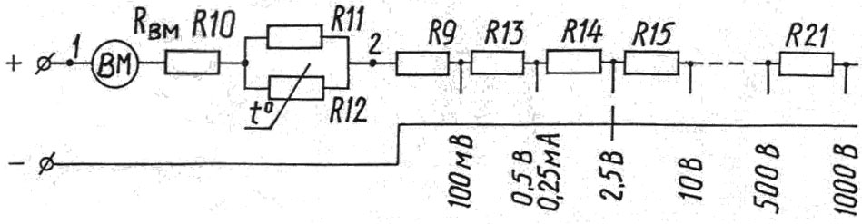
Pic.4.2 Measuring rate voltage scheme with the help of additional resistors
All scheme elements of CD, namely, shunts, multiplier resistors and rectifier transducer are seated inside the CD body. Together with an MM, switches and protection circuit from overload, they compose one compact device.
A connection MM scheme, universal shunt and compensation elements of temperatures error in d.c. measuring mode are shown on fig.4.1.
At that universal shunt permanently, irrespective of operating switch position, is connected to MM. At switching of operating range shunt is not disconnected from MM, only a load circuit opens. Due to that, an occasion of MM damage by high current of researched object is excluded.
At any operating range some resistors are connected with MM in series, as multiplier, and others are connected in parallel, as shunt. On fig.4.1 an operating switch is set on limit of 5 mA. A load current IL is divided on two parts: Imm current flows across MM and series connected to it resistors R10, R11, R12, R7, R8. It does not exceed of MM full-scale deflection current. A superfluity part of load current flows across the shunt resistors ( R1, …, R0) for this operating range, namely current of the shunt Is.
At any operating range shunt resistors and multiplier resistors are switched so that current not more than the MM full-scale deflection one flows across the MM.
R10 is an adjusting resistor. It complements the resistance of MM to the calculated magnitude of the MM coils winding’s technological process peculiarities of (resistance’s dispersion of the same type coils).
Thermoresistor R12 and adjusting resistor R11 are intended results in a perceptible for compensation of CD temperature error. Under change, for example, at augmentation the temperatures of environment, the resistance of copper MM coil is increased, that could resulting lessening
Усі елементи схеми КП – шунти, додаткові резистори та випрямний перетворювач розташовані всередині корпусу. Разом із ВМ, перемикачами та схемою захисту від перевантаження вони складають єдиний компактний прилад.
Схема з'єднання ВМ, універсального шунта та елементів компенсації температурної похибки в режимі вимірювання постійних струмів показана на рис.4.1.
При цьому універсальний шунт постійно, незалежно від позиції перемикача межі вимірювання, приєднаний до ВМ. При перемиканні межі вимірювання шунт ні на мить не від'єднується від ВМ, а розривається тільки ланцюг навантаження. Завдяки цьому виключається можливість пошкодження ВМ великим струмом досліджуваного об'єкту.
На будь-якій межі вимірювання деякі резистори виявляються приєднаними до ВМ послідовно, як додаткові, а останні приєднані паралельно, як шунт. На рис.4.1 перемикач межі вимірювання встановлено на межу 5 mА. Струм навантаження Iн розгалужується на дві частини. Через ВМ і послідовно з'єднані з ним додаткові резистори R10, R11, R12, R7, R8 протікає струм Iвм, який не перевищує струм повного відхилення ВМ. Через шунт, яким відповідають, для цієї межі вимірювання резистори R1...R6, протікає надлишкова частина струму навантаження, а саме – струм шунта Iш.
За будь-якої межі вимірювання резистори шунта та додаткові резистори перемикаються так, щоб через ВМ протікав струм, який не перевищує струм його повного відхилення.
Резистор R10 – підгоночний. Він доповнює опір ВМ до розрахункового значення (особливості технологічного процесу намотки рамок ВМ призводять до помітної розбіжності опорів однотипних котушок).
of current and MM indications. In order to avoid it, a special semiconductor resistor R12 is connected in series with MM. The resistance of one at temperature increase is reduced (it has a negative TCR temperature coefficient of resistance). By adjusting manganin resistor R11 it is obtained that in working diapason of CD temperatures, a lessening of summary resistance R11; R12 was such, as an augmentation of the coil resistance that will ensure current independence on temperature. All resistors of CD except R12 are made of manganin, i.e. their resistance practically does not depend on temperature (TCR=0). Application of this copper, manganese and nickel alloy for shunts and multiplier resistors, due to its high electric resistivity, to resistance stability for a long time, to small TCR, to fabric ability (specificity, it is simply to solder).
A scheme of MM with multiplier resistors connection in measuring mode of d.c. voltages is shown on fig.4.2.
Multiplier resistors are selected after resistance so, that at any operating range, input resistance of CD changes in proportion to operating range.
Input resistance of CD is dependent on sensibility of MM and amounts, usually, for most cheap and primitive testers of (5…10), and for advanced, more perfect expensive devices, nearly 20 Ω/V. The schemes of universal shunt and multiplier resistors at measuring on alternating current remain such as on direct current.
But a connection scheme of MM is changed to points 1 and 2 on fig.4.1, instead of MM and resistors R10… R12, circuit with semiconductor rectifier diodes VD1 and VD2 is connected
струму, а, значить, і показів ВМ. Щоб уникнути цього, послідовно з ВМ приєднують спеціальний напівпровідниковий терморезистор R12, опір якого при зростанні температури зменшуєтья (він має від'ємний ТКО – температурний коефіцієнт опору). Підгоночним манганіновим резистором R11 домагаються, щоб у робочому діапазоні температур КП зменшення сумарного опору R11, R12 було таким же, як і збільшення опору рамки, що забезпечить незалежність струму від температури. Усі резистори КП, окрім R12, манганінові, тобто їх опір практично не залежить від температури (ТКО=О). Застосування цього сплаву міді, марганцю та нікелю для шунтів і додаткових резисторів завдячує його високому питомому електричному опорові, стабільності опору на протязі тривалого часу, малому ТКО, технологічності (зокрема, його просто паяти).
Схема з'єднання ВМ з додатковими резисторами у режимі вимірювання постійних напруг наведена на рис.4.2.
Додаткові резистори підібрані за опором так, що на будь-якій межі вимірювання вхідний опір КП змінюється пропорційно межі вимірювання.
Вхідний опір КП залежить від чутливості його ВМ і складає, звичайно, для найпростіших, найдешевших тестерів (5...10), а для досконаліших, дорожчих приладів близько 20 кΩ/V. При вимірюваннях на ЗМІННОМУ струмові схеми універсального шунта та додаткових резисторів залишаються такими ж, як і на постійному.
Проте змінюється схема приєднання ВМ: до точок 1 і 2 на рис.4.1 замість ВМ і резисторів R10...R12 приєднується ланцюг із напівпровідниковими випрямними діодами VD1 та VD2
(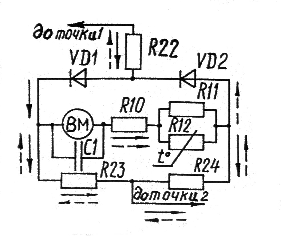
 fig.4.3).
Directions of currents of this scheme at positive (when on point 1 is
plus, and on point 2 is minus) and at negative (when plus is on point
2, and minus is on 1) half periods are shown, accordingly, by
continuous and dotted lines. It is important that across the MM, a
current flows in one direction at half of period that is why such
rectifier transformer is named a full-wave mode.
fig.4.3).
Directions of currents of this scheme at positive (when on point 1 is
plus, and on point 2 is minus) and at negative (when plus is on point
2, and minus is on 1) half periods are shown, accordingly, by
continuous and dotted lines. It is important that across the MM, a
current flows in one direction at half of period that is why such
rectifier transformer is named a full-wave mode.
Fig.4.3 Scheme elements of the combined device for measuring alternating currents and voltages
For measuring of a resistance by CD, different ohmmeter schemes are used. For measuring of the most widespread in practice, middle resistance (approximately from 100Ω to 1MΩ) it is expediently to use a series ohmmeter circuit (fig.4.4). At that the researched resistor and MM are connected in series and across them the same current flows. The highest magnitude of this current, what means that the full right side pointer the scale deflection will be at the minimum researched resistor (Rx 0)resistance. It means that zero mark of scale (Rx=0) of this ohmmeter will be not on left (as in ammeter and
(рис.4.3). Напрямки струмів цієї схеми в позитивний (коли в точці1 плюс, а точці 2 - мінус) і в негативний (коли плюс в точці 2, а мінус - в 1 ) напівперіоди показані, відповідно, суцільними та пунктирними лініями. Важливо, що через ВМ струм протікає в одному напрямку в обидва напівперіоди, тому такий випрямний перетворювач називають двопівперіодним.
Рис. 4.3 Елементи схеми комбінованого приладу для вимірювання змінних струмів і напруг
Для вимірювання опорів в КП використовують різні схеми омметрів.
Для вимірювання найпоширеніших у практиці, середніх, опорів (приблизно, від 100 Ω до 1 МΩ) доцільно застосовувати послідовну схему омметра (рис.4.4). При цьому досліджуваний резистор і ВМ з'єднуються послідовно, і через них протікає один і той же струм. Причому, найбільший розмір цього струму, а, значить і відхилення праворуч по шкалі стрілки ВМ, буде при найменшому опорі досліджуваного резистора R→0. Тобто нульова позначка шкали (Rх = 0) цього омметра буде не з лівого (як у амперметра та
voltmeter), but on the right side of scale. A special electric zero regulator Rreg is appointed for accurate setting of pointer on zero mark (this recommends to make even after short interruption in work of CD) (fig.4.4). It is shown on front CD panel zero adjuster is a regulator of mechanical zero scale mark. It is also shown on MM panel. At that the AB conductor probes by which Rx must be joined to CD are locked between oneself (fig.4.4), and then by regulator Rreg the pointer is set on ‘zero k’ (on the right side of scale). Necessity of such, fairly often, corrections of ‘electric zero’ are caused to the development by exhaustion (by discharge) of low-powered dry feeding cells are used in CD.
A t
further AB probes breaking and its connecting to the researched
resistor Rx, across MM flows a current Imm=U/(Rx+Rmm+Rper+Rm), less
than at Rx=0, and MM pointer deflects on angle, that is coincided to
resistance Rx. A resistor Rs, usually has a few fixed magnitudes,
according to changing of resistance measuring operating range, for
example, k
x 1; k
x 10; k
x 100.
t
further AB probes breaking and its connecting to the researched
resistor Rx, across MM flows a current Imm=U/(Rx+Rmm+Rper+Rm), less
than at Rx=0, and MM pointer deflects on angle, that is coincided to
resistance Rx. A resistor Rs, usually has a few fixed magnitudes,
according to changing of resistance measuring operating range, for
example, k
x 1; k
x 10; k
x 100.
Fig.4.4 Series ohmmeter scheme for Fig.4.5 Shunt-
measuring of middle resistance type ohmmeter scheme for
measuring of small resistance
For measuring of a small resistance (less than 100) researched resistor Rx to MM connection of scheme is better (fig.4.5). At that, if conductors with the AB probes, used for joining of a
вольтметра), а з правого боку шкали. Для точного встановлення стрілки на нульову позначку, а це рекомендується робити навіть після короткої перерви у роботі з КП, призначений спеціальний регулятор електричного нуля Rрег (рис.4.4.), виведений на лицьову панель КП (регулятором «механічного нуля “ ВМ є коректор, шліц якого виведено на панель ВМ). При цьому замикають між собою щупи провідників АБ, (рис.4.4) якими повинен приєднуватись Rх до КП, і регулятором Rрег встановлюють стрілку на позначку “0кΩ“(з правого боку шкали). Необхідність такої, доволі частої, корекції “електричного нуля” і спричинюється виснаженням (розрядкою) малопотужних сухих елементів живлення, застосовуваних у КП.
П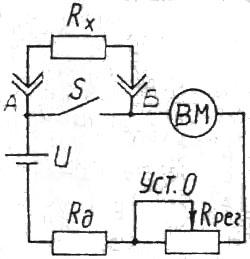 ри
подальшому розмиканні щупів АБ і
приєднанні їх до досліджуваного резистора
Rх через ВМ протікає
струм Iвм = U
/ ( Rх + Rвм
+ Rрег + Rд
), менший, ніж при Rх
= 0, і стрілка ВМ відхиляється на
відповідний опорові Rх
кут. Резистор Rд,
звичайно, має кілька фіксованих значень,
відповідно зміні межі вимірювання
опору, наприклад: кΩ х 1; кΩ х 10; кΩ х
100.
ри
подальшому розмиканні щупів АБ і
приєднанні їх до досліджуваного резистора
Rх через ВМ протікає
струм Iвм = U
/ ( Rх + Rвм
+ Rрег + Rд
), менший, ніж при Rх
= 0, і стрілка ВМ відхиляється на
відповідний опорові Rх
кут. Резистор Rд,
звичайно, має кілька фіксованих значень,
відповідно зміні межі вимірювання
опору, наприклад: кΩ х 1; кΩ х 10; кΩ х
100.
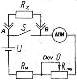
Рис. 4.4. Послідовна схема омметра Рис. 4.5 Паралельна вимірювання середніх опорів схема омметр для
вимірювання малих опорів
Для вимірювання малих опорів (менших за 100 Ω) кращою є паралельна схема (рис.4.5) приєднання досліджуваного резистора Rх до ВМ. При цьому, якщо провідники зі щупами АБ, призначені для приєднання
researched resistor Rx are opened (Rx∞), the largest current flows across MM. It deflects a pointer to the right side of scale ‘’ to mark ‘’. The electric zero adjuster, as in previous case, is shown on the front panel of CD. It sets up the pointer on the last right scale mark (now it is not ‘0 k’, but ‘’). In this case none zero scale mark is corrected under closed probes, but the infinity () scale mark is corrected by it under open probes.
After correction of ‘’ researched resistor Rx is joined to AB probes (fig.4.5). It shunts MM overleaping a part of current by MM passing, due to what its pointer deflection will decrease according to Rx resistance.
A series scheme is adopted for high resistance measuring (merger mode), but for increasing of current across MM, in series with researched resistor Rx an external additional source of feeding by voltage of (12…15) V is connected. On fig. 4.6 a front CD panel of studied in this laboratory work Ц4317 type is shown. For joining of researched object the device has two cleats with sockets 12 (marked ‘’left, is named common) and socket, marked ‘+’ between them. A multiple-position switch 9 is used for choice of measure mode (V, A,) and the operating range. By three-position switch 11 measuring mode of direct (a position is marked ‘ – ‘), alternating (mark is ‘~’) current and voltage, or resistance (mark is ‘Rx’) is chosen. On scale 2-5
and on front CD panel marks and lettering is plotted. By them one can see a destination of scale, mode and operating range measurand, devices accuracy class for different measurements and other important technical descriptions. For example, in measuring mode of alternating currents and voltages, a CD has accuracy class of 2.5, besides of 0.5V operating range (the lowest and the most short scale), for which it is equal to 4.0.
For measuring result counting in necessary units of measurand (not simply in amount of scale division)
досліджуваного резистора Rх розімкнуті ( тобто Rх → ∞ ), через ВМ протікає найбільший струм, який відхиляє стрілку праворуч по шкалі “Ω” до позначки “∞”. Як і в попередньому випадку, для точного встановлення стрілки на крайню праву позначку шкали (тепер вона відповідає не “0кΩ”, а “∞” ), служить виведений на передню панель КП електричний коректор Rрег (тільки тепер ним коректують не нульову позначку опору при замкнутих щупах, а нескінчену позначку опору при розімкнутих щупах.
Після корекції “∞” до щупів АБ (рис.4.5) приєднують досліджуваний резистор Rх, який шунтує ВМ, перепускаючи частину струму в обхід ВМ, завдяки чому відхилення його стрілки зменшиться відповідно опору Rх.
Для вимірювання великих опорів (режим мегомметра) застосовується послідовна схема, але для збільшення струму через ВМ послідовно з досліджуваним резистором Rх вмикають ще й зовнішнє додаткове джерело живлення напругою (12...15) В.
На рис.4.6. зображена передня панель КП типу Ц4317, який вивчається в цій лабораторній роботі. Для приєднання досліджуваного об'єкту прилад має два затискачі з гніздами 12 (лівий, позначений ”*” називають спільним) та гніздо, позначене “+Ω” між ними. Багатопозиційний перемикач 9 призначений для вибору виду вимірюваної величини ( V, А, Ω ) та межі її вимірювання. Трипозиційним перемикачем 11 обирають режим вимірювання постійного (позиція позначена “-“), змінного (позначка “~” ) струмів та напруги, або опору (позначка “Rх”).
На шкалах 2-5 та на передній панелі КП нанесені позначки та написи, за якими можна визначити призначення шкали, вид і межу вимірюваної величини, класи точності приладу для різних вимірювань і інші важливі технічні характеристики. Наприклад, в режимі вимірювання змінних струмів і напруг КП має клас точності 2,5, окрім межі 0,5 V (найнижча та найкоротша шкала), для якої він дорівнює 4,0.
Для відліку результату вимірювання в потрібних одиницях вимірюваної величини (а не просто у кількості поділок шкали)
foremost, dependency on switches positions 9 and 11, we have determine, which from device scales is needed to use. For this suitable symbols: ‘- VA’, ‘~VA’, ‘’, ‘k’, ‘M’, ‘~0.5V ’, ‘dB’ are plotted on the right side of each scale.
Farther a scale interval of selected scale ‘~VA’ has to be calculated by
Cdiv=operating range (necessary units of measurand)/complete number of selected scale divisions
For easy calculation (when the scale interval is multiple to10), a scale “- VA” has 3 complete number files of amount scale divisions – 10, 25, 50. The selection of definite file is depended on operating range. Finally, a device pointer indication in amount of selected scale divisions should be multiplied by the scale interval, calculated before.
Been used of scales ‘k’, ‘M’, the pointer indication on this scale is necessary to multiply by the suitable coefficient dependency on switch 9 position: k x 1, k x 10, k x 100, or M x 1. For example, if switch 9 sets Un – 29V position, and switch 11 – in position ‘~’, the scale 3 is used:
C division = 25 V / 50 divisions = 0.5 V / division.
If CD pointer (fig.4.6) shows 26 divisions on the scale 3, then measured voltage of the alternating current is:
U = 26 divisions x 0,5 V / division = 13 V.
Knowing accuracy class of device in this mode, namely = 2.2, permissible absolute error of measurement Δp can be calculated: Δp = γ*Un / 100 = 2.5 x 25 V / 100 = 0.625 V
Simpler calculation of a permissible absolute error: it is equal to 2.5 percentages (because the accuracy class equals 2.5) from 25V (because operating range is 25V).
Finally, the measuring result can be considered as:
U = (13.000 ± 0.625) V, i.e. an actual voltage value; when CD is shown of 13 V, is not less then 12.375 V and not more then 13.625 V.
At measuring of resistance (accuracy class of 1.5) and voltages in decibels (accuracy class of 2.5) a permissible absolute error is calculated at the first in the same
перш за все, залежно від позицій перемикачів 9 та 11, визначають, якою з багатьох шкал приладу треба
користуватися. Для цього праворуч кожної шкали нанесені відповідні символи: “-VA” , “~VA” , ”Ω” , “кΩ” , “МΩ” , “~0,5V” , “dB” .
Далі обчислюють ціну поділки обраної шкали “~VA” за формулою Споділки = межа вимірювання ( у потрібних одиницях вим.величини)/ повне число поділок обраної шкали
Для зручності підрахунків ( щоб ціна поділки була кратною 10 ) шкала “-VA” має 3 ряди чисел повної кількості поділок-10,25,50. Доцільність обрання певного ряду залежить від межі вимірювання.
Нарешті, покази стрілки приладу в кількості поділок обраної шкали треба помножити на обчислену раніше ціну поділки.
При користуванні шкалою “кΩ” , МΩ” покази стрілки за цією шкалою треба множити на відповідний коефіцієнт залежно від позиції перемикача 9: кΩ х 1; кΩ х 10; або кΩ х 100 чи МΩ х 1.
Наприклад, якщо перемикач 9 стоїть у позиції UN = 25 V,а перемикач 11 у позиції “~”, користуються шкалою 3. При цьому ціна поділки:
Споділки = 25 V / 50 поділок = 0,5 V/поділку.
Якщо стрілка КП (рис.4.6) показує за шкалою 3 26 поділок, то вимірювана напруга змінного струму:
U = 26 поділок x 0,5 V/поділку = 13 V Знаючи клас точності приладу в цьому режимі, а саме = 2,5, можна обчислити допустиму межу абсолютної похибки вимірювання ∆д: ∆д = UN / 100 = 2,5 x 25V / 100=0.625V Простіше обчислення межі допустимої абсолютної похибки: вона дорівнює 2,5 відсотки (бо клас точності 2,5) від 25V (бо межа вимірювання 25V).
Остаточно - результатом вимірювання можна вважати:U = ( 13,000 ± 0,625 ) V,тобто, дійсне значення напруги, коли КП показав 13V, не менше за 12,375V і не більше за 13,625V. При вимірюванні опорів (клас точності 1,5) і напруг в децибелах (клас точності 2,5) межа допустимої абсолютної похибки спочатку числюється в тих самих
units, that fiducially value of scale (usually, in millimeters), and then very approximately interpolated
independence on pointer indication, in measurand units (, k, M, dB).
CD Ц4317 has a special automatic device defense scheme from electric overloads. If measurand exceeds fixed by switch 9 measuring limit over 6 once, device circuit breaker is activated, preventing device damage. In order to return CD to operation the button 7 should be pressed only after clearing up and removal of working cause auto protection.
By means of CD in resistance measuring mode the semiconductor diodes and transistors serviceable condition, condensers, transformers and other elements and knots of electric schemes can be checked.
At researching of semiconductor diode it is necessary to remember, that its resistance in straight direction (when ‘+’ enclosed to anode, and ‘- ’ to cathode) is small, from ones to hundreds ohms, and into reverse direction – increases into hundreds, and even into many thousands times.
That is why it is expediently to measure a straight resistance operating ranges, appointed for small resistance (‘kΩ’ x 1 or ‘Ω’), and reverse – on ‘kΩ x 100’ or sometimes even ‘MΩ’. Besides, remember from physics courses that voltage-current characteristic of p-n barrier in straight direction is nonlinear. Forward resistance of semiconductor diode depends on voltage applied to it. To be convinced of this it can be measured on different CD operating ranges. Pay attention to the fact that in the resistance measuring mode an internal CD feeding source cleat (‘+’) is not right as in the measuring mode of direct currents or voltages, but left marked ‘*’.
Checking out a transistor marking and equivalent scheme of which is shown on fig. 4.7, you have to ensure in safety of its emitter and collector and emitter measuring in two directions (exchanging the AB probes by places) resistance between collector and emitter. Very little almost zero resistance will show the failure of transistor.
одиницях, що й нормоване значення шкали (звичайно, у міліметрах), а потім, дуже приблизно, може бути інтерпольована, в залежності від положення стрілки, в одиницях вимірюваної величини ( Ω , кΩ , МΩ , dB ).
В КП Ц4317 є спеціальна автоматична схема захисту приладу від електричних перевантажень. Якщо вимірювана величина перевищує встановлену перемикачем 9 межу вимірювання понад 6 раз, спрацьовує автовимикач приладу, запобігаючи його пошкодженню. Відновити дію КП можна натисканням кнопки 7, лише після з'ясування та усунення причини спрацювання автозахисту.
За допомогою КП у режимі вимірювання опору можна перевірити справність напівпровідникових діодів і транзисторів, конденсаторів, трансформаторів та інших елементів і вузлів електричних схем.
При дослідженні напівпровідникового діода слід пам'ятати, що його опір у прямому напрямку, тобто коли “+” прикладено до анода, а “-“ до катода (гострого кінця стрілки, яким умовно позначається діод на схемах) невеликий, від одиниць до сотень омів, а в зворотньому-збільшується в сотні, а то й у багато тисяч разів. Тому вимірювати прямий опір доцільно на межах, призначених для малих опорів (“кΩ” х 1 або “Ω”), а зворотній на “кΩ х 100” або, іноді, навіть “МΩ” . Окрім того, згадайте з курсу фізики, що вольтамперна характеристика р-n переходу в прямому напрямку нелінійна. Отже, прямий опір напівпровідникового діода залежить від прикладеної до нього напруги. Впевнитись у цьому можна, вимірюючи його на різних межах вимірювання КП.
Зверніть увагу також на те, що в режимі вимірювання опорів, коли працює внутрішнє джерело живлення КП, “плюсовим” є не правий, як у режимі вимірювання постійних струмів або напруг, а лівий затискач, позначений “*”.Перевіряючи транзистор, умовне позначення та еквівалентна схема якого зображені на рис.4.7., впевніться в цілості його емітерного та колекторного

Fig. 4.7. Conditional designation and equivalent scheme of transistor.
The good condenser condition can be determined by means of CD on resistance measuring mode (Rx). At connection at CD probes two and uncharged condenser, condenser begins charging from internal CD power source what is attested by sharp pointer deflection towards the small resistance. Will condenser is charging (charging time depends on its capacity), a charging current diminishes, and resistance increases that is attested by the gradual pointer returning to marks of big resistance. A complete charged condenser with high-quality isolation, a direct current does not pass by it resistance comes around endlessness.
An electrolytic condensers in this respect are something worse than for example, a mica one, that is why its resistance in charged condition has rather high but final magnitude (pay attention that these condensers are polar, they have ‘+’ and ‘-’ electrodes). Described process can be observed only at testing of enough big capacity condensers (in units and more noticeably in tens of microfarad). For condensers of lesser
пробою так званої “підкладки”, вимірявши в двох напрямках (міняючи щупи АБ) місцями, опір між колектором і емітером. Дуже малий, майже нульовий, опір засвідчить про несправність транзистора.