


TURBOGENERATOR
A turbo-generator comprising a shaft, on which is positioned an axial ventilator, a cover that divides an inflow chamber for a cooling gas transported by the axial ventilator from an outflow chamber for this cooling gas, and a cylindrical channel segment that is positioned coaxially to the axial compressor and surrounds the axial compressor radially, whereby the inflow chamber comprises an asymmetrical cooling gas supply, and whereby in the inflow chamber means for homogenizing the cooling gas supply to the axial ventilator are provided. In order to improve the cooling, and therefore the efficiency of the machine, the inflow chamber forms a rotation-symmetrical annular chamber in the region of an inflow opening of the channel segment. A cylindrical annular collar is positioned coaxially to the axial ventilator within this annular chamber. The annular collar projects axially into the annular chamber and forms a completely surrounding, radial throttling gap at the inflow opening.
Introduction. Advantages of powerful turbogenerators with water and oil cooling
At water and oil cooling of the turbogenerators, it will be done:
direct cooling of the active and design parts of stator by insulating oil at filling of stator by this oil, at that, the oil volume in stator is limited by stator case, end shields and insulation cylinder mounted at the air gap and fixed at the shields;
paper and oil insulation for stator winding;
water cooling of rotor winding.
The experience of many year service of TBM-60 turbogenerators of capacity 60 MW (since 1963), TBM-300 of capacity 300 MW (since 1968) and TBM-500 of capacity 500 MW (since 1978) with such cooling system and stator winding insulation, and also, the results of special researches and industrial tests of these turbogenerators have shown that the water and oil cooling system provides a number of the advantages in comparison with the other cooling and insulation systems.
The main advantages:
1. High reliability that is reasoned by:
absence of big number of the supplies of cooling liquid to stator winding and elements as a supply and drainage of cooling oil for winding bars and stator core are done at the oil filled cavities, at that, all hydraulic circuits inside the stator do not require the guaranteed tightness as at water cooling;
high level of reserve of electric strength and resistance of paper and oil insulation to the mechanic influences at vibrations and deformation s of bars that allowed to define the periodicity of the capital repairs of stator in 10 years instead of 4-5;
protection ability of inner stator cavity from outer influences (moisture, dust and others).
2. The higher overloading abilities and more extended capabilities of operation at abnormal modes (operation at under-excitation is limited by static stability, at asynchronous mode, it is admitted the durable operation at active power 40 % of rated one, at asymmetrical load, it is admitted the durable operation with inverse current up to 10 % of rated value of stator current).
3. The high efficiency at whole operation range of the loads due to relatively low level of the mechanical losses at generator and additional losses at winding and end parts of stator.
4. The ability of preventing determination of core status and insulation of stator winding by gas chromatography method.
5. The relative simplicity of mounting and maintenance.
6. The higher repair ability of stator winding as the over-monolithising for the straight portions is absent, and a restoration of the case insulation of the bars by paper tapes can be done beyond the plant facilities.
7. The ability of the manufacturing of the turbogenerators for optimum voltage assuming the machine parameters.
Intention
The turbogenerator is intended for power generation at direct coupling with steam turbine.
Service contidions
The sea level is not more 1000 m. The range of admitted ambient temperature:
- upper value +40 C
-lower value +5 C
The environment is not explosion hazardous, no dust at the concentrations reducing the parameters of turbogenerators at non-admitted limits.
Technical data
Parameter |
ТВН-320-2 |
Rated active power, kW |
320000 |
Full power, kVA |
376500 |
Power factor |
0,85 |
Voltage, V |
20000 |
Current, A |
10870 |
Frequency, Hz |
50 |
Phase connection |
“double star” |
Speed, rpm |
3000 |
Efficiency, % |
98,9 |
Field current, A |
4600 |
Field voltage, V |
290 |
Short circuit ratio |
0,5 |
Transit inductance, r.u. |
0,34 |
Over-transit inductance, r.u. |
0,21 |
Static overloading, r.u. |
1,7 |
Flow of insulating oil through stator, m3/h |
500 |
Temperature of cooling water at input of heat exchangers of oil and distillate, C |
32 |
Flow of distillate at rotor cooling system, m3/h |
65 |
Temperature of cooling oil and distillate at input of generator, C |
40 |
Flow of oil per bearing, l/min. |
400 |
Mass,t: - total - stator (for transportation) - rotor |
290 215 49,2 |
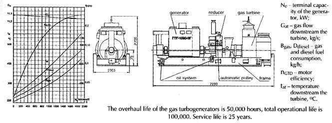
Function of efficiency against load
Load,r.u./MW |
0,5/160 |
0,75/240 |
1,0/320 |
1,1/352 |
Efficiency, % |
98,85 |
98,95 |
98,9 |
98,85 |
Admitted temperatures of heating
- stator winding, C 105
- stator core, C 105
- rotor winding (on resistance), C 75
- insulating oil at output of stator, C 90
- distillate at output of rotor, C 85
Admitted abnormal operation modes of turbogenerator
the turbogenerator admits the durable operation at asymmetrical load if the currents in phases do not excess the admitted value for these conditions of operation of the turbogenerator at symmetrical load, and inverse current, at that, must not excess 8 % of rated value of stator current.
the turbogenerator admits an operation at under-excitation mode at rated active power and power factor as 0,95 (leading).
The turbogenerator admits an operation at asynchronous mode during 15 minutes at consuming active power not more 60 % of rated one, during 30 minutes – at consuming power not more 50 % of rated one, and durably – at consuming power not more 40 % of rated one.
Desing version
The turbogenerator version is horizontal.
The stator core and winding are immersed into the insulating oil. The oil volume filling the stator is limited by case, end shields and insulation cylinder placed into the split of stator core. The insulation cylinder and end shields, at the places of joining to stator case, are sealed with the rings of rubber cord. To extract the rotor for its overview and prophylactic repair, it is not necessary to drain oil from stator and remove the end shields. The stator case is one part and welded. The stator core is assembled of the insulated segments of electric steel in which, at stamping, the narrow rectangular holes creating the axial ducts at the core over which the insulating oil cooling the core floats, are cut off. The pressed core is laid axially and held by stuck packages and clamping non-magnetic elements. In the case, the core is fitted rigidly. The stator winding is three phase, two layer, with shortened pitch. The bars of the winding are done of the alternating hollow and solid wires. The oil floating over the ducts of the hollow wires cools the bars. The phases of the winding are connected into star.
The line and neutral terminals of the stator winding are led out the case of stator through the isolators and placed at the bottom of case. The plate on which the terminals are fitted, is designed to connect the closed current supplies.
The rotor is done of the integral forging of special alloyed steel. The rotor winding consists of the concentric coils fabricated of the hollow copper with silver addition. The straight portions of the winding are fitted by slip rings of alloyed non-magnetic stainless steel. The cooling of the rotor winding is done by distillate which floats over the ducts of the wires. All coils over distillate are connected in parallel. The water supply and its drainage are fulfilled through the central hole of the shaft over the concentrically mounted pipes of stainless steel.
The slip rings are done of special steel and set onto the console shaft end. To cooling of the slip rings and brushes and remove the brush dust from an area of brush and contact device, between the slip rings on a shaft, the fan is mounted. The turbogenerator bearings are outboard thrust ones. The bearing from a side of the slip rings has the self-mounting insert with spherical setting in case. The bearing from a side of the turbine is built into the turbine case and supplied with the turbine.
The oil supply into the turbogenerator bearings are fulfilled from the lubrication system of the turbine bearings. To cool the turbogenerator, on the power plant, the cooling systems for stator and rotor with usage of equipment supplied with generator, must be mounted. The cooling of stator by insulating oil and of rotor by distillate is fulfilled over the close loop: electric pump – cooler – filter – cooled item – electric pump. For a circulation of oil, the watertight pumps without seals are used. At each system, the reserve pump, reserve cooler, reserve filter are installed. At cooling system of stator, for a compensation of temperature changes of insulating oil volume filling stator and system, at the input of the pumps, the extending sets are connected. One of them is operating, other is reserve one. The insulating oil purified from the mechanical additions and water with oil station of the power plant, before the stator filling and its cooling system, is degassed. The equipment for degassing and filling of stator and its system under vacuum, is supplied with the generator. One set of such equipment provides the maintenance of two or three identical turbogenerators installed at main room of the plant. The excitation system of the turbogenerator is thyristor one done with self-excitation circuit.
Supply scope of turbogenerator
the turbogenerator with sole plates and anchor pins;
stator cooling system;
rotor cooling system;
excitation system;
spare parts;
mounting tools and special instruments;
service documents.
Quality and guarantees
The development, conquest of the production, manufacturing and tests of the turbogenerator, NPO “ELSIB” OAO carries out in accordance with the requirements of ISO-9001-94 standard.
The turbogenerator meets the RF standards and IEC recommendations.
The enterprise guarantees the correspondence of the turbogenerator to the requirements of the standards at the condition of the keeping of service, transportation and storage rules stated by TU by customer.
The warranty term stated for the turbogenerator is 3 years since a date of commission, and for the turbogenerators intended for export – 1 year since a date of commission but not more 3 years since a moment of passage of the turbogenerator across the state boundary of RF.
Air-cooled turbogenerators
Convenience, simplicity and flexibility T Air-cooled generators is well suited to the cyclic and peak operating mode, allow achieving the high extent of automatization of the technological processes, reducing the operation costs significantly. Almost all generators supplied by “ELSIB” with capacity rated from 6 to 20 МW have the indirect cooling system of the rotor winding that provides the higher reliability and durability. The use of the joint insulating impregnation of the stator winding and core provides a higher resource on a capacity, heat loads and minimizes the vibration values. The coil and coil-bar stator windings allow to reduce a length of generator and increase its specific weight characteristics. A proved materials and excellently presented itself insulation system exclude an appearance of the damages at the coronas. The thermal-resistance insulation class is “F”. At the rated and maximum modes, it provides the use of “B” class insulation that allows ELSIB generators to operate at the extended modes and at the wider range of the environment. This characteristic is especially important for generators matched to the gas turbines, because capacity of those notably increases at the reduction of the ambient temperature. Air-cooled
generators operate with closed-loop cooling system. The air
circulation is provided with the axial fans on the shaft of rotor,
and the air-to-water heat exchangers located on each side of
generator remove heat from the air. The generators of power rating from 25 to 160 MW are produced at the one-piece welded case of cylindrical shape. The design of case provides the high rigidity and strength, that allows generators to operate reliably and stably at all operation modes include cycled load, peaking duty, overload modes. This is pledge of the generator durability and reliability providing for its high operational characteristics. The air circulating inside the generator over the close loop is cooled at the air-to-water heat exchangers built in the stator case horizontally. The heat exchangers of 160 MW generator located on each side of the stator. The simple and effective cooling system is slightly soiled, that significant assists to keep relatively low heat level of the active parts and the high effectiveness of the generator at the whole lifetime. Many design solutions for air-cooled turbogenerator were based on the reliable and proved by the long time service decisions realized before at the hydrogen-cooled generators of the similar class. Due to that, the “ELSIB” air-cooled generators imbibed all the best and proved existing today at the Russian generator technology. Moreover, they possess the unique capability to be transformed into hydrogen-cooled generator with the slight modernization fulfilled on site. At the same time the capacity of generator can be increased to 150 %. This gives the additional opportunities for our customers to plan the power system changes and reconstructions. The design and manufacturing technology of the generators guarantee the high maintainability of the equipment that at great extent reduces the possible future costs of our customers. Moreover, these generators with the minimum costs can be assembled on the existing foundations of the retired turbogenerators of the same capacity class with air and hydrogen cooling system. |
 urbogenerators
with air-cooling system of “ELSIB” production are the
optimum choice for the power system application that demand
flexibility and simplicity of operation and service.
urbogenerators
with air-cooling system of “ELSIB” production are the
optimum choice for the power system application that demand
flexibility and simplicity of operation and service.
Liquid-cooled turbogenerators
S The liquid-cooled turbogenerators are well suited to central large power plants with power blocks of large output capacity. The requirements for a reliability and stable operation in the power grid of these generators are especially high. The liquid-cooled generators of ТВН type supplied by “ELSIB” are unique equipment without analogues in the world generator technology. The construction peculiarity is a filling of the stator volume with the heat resistance dielectric liquid that is also the cooling medium and a stator insulation system component (like in oil transformer). The dielectric liquid is circulated in a closed loop to remove the heat from the active elements of stator and cools at the water heat exchangers located out the case of the generator. The stator volume filled with the liquid is limited by the end shields, stator case, and from the side of a gap between stator and rotor - by the special dielectric cylinder. The insulation system of stator winding has the significantly more high dielectric strength than other known types of the insulation used at the large turbogenerators. This allows creating the generators with the optimum stator voltage in respect to the main parameters of the machine. The generator rotor is cooled by water supplied and drained through a water-fed device located at the central part of rotor shaft. The supply of cooling water to the rotor winding is provided with the radial units of the water-fed device. The
cooling and insulation systems of ТВН
generator give it the high reliability and provide a lot of the
advantages and unique operational properties. The sufficient
resources on the dielectric strength, heat loads, stability to the
mechanic influences at vibration and deformation of the stator
winding bars and other the design features allow to our customers
to achieve the significant saving of the means and be fully sure
in the reliable operation of these machines.
This happens mainly
due to the followings:
In comparison with the other generators of large capacity the TBH generators have simple design and production workability that provide the high reliability and durability at the relatively low costs. For design the TBH generators the hydraulic and thermal phenomena at ducts of core and stator and rotor windings on the models, samples and test platforms were investigated. The researches done with the special platforms and natural generators defined the design of the end conical packets of stator core, wedge area of rotor and other assemblies. |
 olution
for the maximum loads
olution
for the maximum loads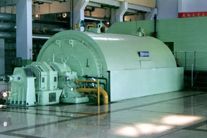
A turbo generator is a turbine directly connected to an electric generator for the generation of electric power. Large Steam powered turbo generators (steam turbine generators) provide the majority of the world's electricity and are also used by steam powered, turbo-electric ships.
Turbo Generator basic model of Wuxi HWATAN Electric Machinery Co., Ltd.,is the air cooled steam turbine generator which is called QF series in China.For QF steam turbine generator, it is of closed air circling cooling system, with air cooler mounted underneath the generator frame air exit. The rotor is made of complete steel forging, mounted with axial flow or centrifuging fans at both ends.
Singapore Polytechnic

Singapore Maritime Academy

&
Maritime Institute Of William Barentsz

Bachelor Degree in Maritime Operations (BMO)
Diesel Technology & EmissionsAssignment
WASTE HEAT RECOVERY
Lecturer: MR. KALYAN CHATTERJEA
Assignment done by: Tam Kong Whee
Date: 4th September 2006
CONTENTS
1. INTRODUCTION AND OVERVIEW---------------------------------------------PAGE 3
2. THE TECHNOLOGY AND ITS WORKING PRINCIPLE-------------------PAGE 4
3. EMISSION CONTROL---------------------------------------------------------------PAGE 7
4. CONCLUSIONS------------------------------------------------------------------------PAGE 8
5. REFERENCES--------------------------------------------------------------------------PAGE 9
1) INTRODUCTION AND OVERVIEW
In the recent days, there has been much emphasis on the emission reduction technology through various innovations. Technology such as direct water injection, Selective Catalytic Reduction (SCR), fuel / water emulsion and injection timing advancement focus more on NOx emission reduction whereas low sulphur fuel is used to reduced SOx emission.
Through such technology, there is always a trade-off between the fuel consumption and the emission reduction. Costly installation and expensive maintenance are also important factors when deciding the type of technology to be used. Currently, most attentions were on NOx and SOx emission reduction with less focus on CO2 emissions. It has also to be recognized that there is very little margin left in the large marine diesel engine for reducing CO2 emission through improving engine thermal efficiency.
In order to achieve both reduction in emission & fuel consumption, the engine maker managed to identify an avenue that is able to address both issues with not only consistency to the engine performance and fuel consumption, but also at the same time provide surplus energy to generate power supply for ship-board services and additional output power for the propeller shaft. This technology is simply known as “Waste Heat Recovery”. With today’s modern low-speed engines having an efficiency of up to 50%, there is still 50% of the fuel input energy to be put to productive use.
The implementation of the waste heat recovery system will not only contribute to emission reduction. In term of commercial aspect, the operation of the vessel will be more economical due to less fuel consumption and surplus electronic power for ship-board services, generated by the waste heat. In the case of a Sulzer 12 RTA6C engine developing a maximum constant output of 68,640 kW, this means that an equivalent quantity of energy is being wasted; this is also equivalent to a consumption of 300 tonnes of HFO. Consider the same amount of fuel that you are able to put to productive use, it not only achieve performance benefit but also economic benefit at the same time.
To get a better overview of the heat distribution in the marine diesel 2-stroke engine, we’ll illustrate using the heat distribution diagram as shown below.
Fig. 1: Heat balance of a
Sulzer 12RTA96C engine shows the potential for waste heat recovery
with current large, low-speed marine engines.
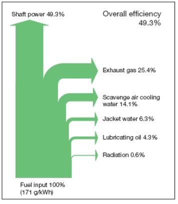
As shown in figure 1, it is apparent that only 49.3% of total power output is generated as shaft power with the majority of other power been distributed through exhaust gas (25.4%), scavenge air cooling (14.1%), jacket water (6.3%), lubricating oil (4.9%) and radiation (0.6%).
From all these heat losses, exhaust gas contribute to the largest portion and this is where we’re going to apply the waste heat recovery system to recover as much heat energy from the exhaust can convert it into other productive output. With that in mind, let’s look at how the implementation of this technology and to what extent it is able to recover the amount of heat loss.
2) The technology and its working principle
As discuss previously, the waste heat recovery system utilized heat energy from the exhaust to generate surplus power output for various purposes. In order to do that, firstly it is important to study the 2-stroke engine cycle and how is it possible to improve the intake efficiency in order to increase the exhaust temperature to achieve higher power output.
Exhaust gas temperature can be increased by adapting the engine for ambient suction air intake. Usually marine engines are designed for intake temperatures of up to 45°C for tropical conditions with turbochargers drawing intake air from the engine room. If instead the intake air is drawn from outside the engine room through an air intake duct, the maximum intake temperature can be assumed to be no more than 35°C. See Figure 2.
Fig.
2 Far
left: Engine room air suction. Left:
Ambient air suction.
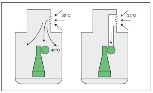
The reason for drawing air from at a lower temperature is simply to increase the density, and subsequently the mass of air required for combustion. This increase in air density, when react with fuel in the combustion chamber, will ignite and produce high exhaust temperature required for the waste recovery system.
As we know, the turbo-charger plays an important part in such operation. To be able to achieve air intake from the atmosphere, in such a case, the turbochargers can be rematched to return the thermal load of the engine back down to what prevails for the intake temperature at 45°C. When considering such a tuning to reach an increased exhaust gas temperature, it is important that the thermal load of the adapted engine is no greater than that of the usual engine so as not to jeopardize engine reliability.
Fig.
3: Schematic
of the Waste Heat Recovery
Plant.

In Figure 3, it briefly illustrates the layout of waste heat recovery plant and the components involved in the cycle.
As shown in the diagrams, the exhaust gas from the main engine will be diverted to the power turbine and the exhaust gas economizer. The power turbine uses a part of the exhaust gas stream {about 10%) from the diesel engine to generate shaft power which can be added to the steam turbine driving the generator.
The turbine is a derivative of a well-proven model of turbocharger turbine with minor adaptations for use as a power turbine. A special matching of the power turbine is necessary for the application in a waste heat recovery system because the turbine operates on a constant-speed operating profile as it is coupled to the generator unlike in a turbocharger with a free-running rotor. The torque of the power turbine is fed to the steam turbine rotor through a reduction gear and an overrunning clutch. The overrunning clutch is needed to protect the power turbine from over speeding in case the generator trips.
With the supplementary shaft power generated by the power turbine, it can allowed a vessel with 3 eight-cylinder Wartsila 32 generating sets with a combined electrical output of some 11 MWe to reduce the installation of one or two fewer auxiliary generating sets than would normally required, taking into account the ship’s capacity for reefer container.
Apart from the power turbine, on the economizer side, the exhaust serves to generate superheated steam and saturated steam for the turbo-generator and shipboard services respectively. In tandem with the heat recovered form this process, it uses 6 MWe Brotherhood turbo-generator set which incorporates a multi-stage dual-pressure turbine and an exhaust gas turbine.
Considering the multi-stage dual-pressure design of the turbo-generator, it is important to generate steam of different pressure and feed them into the different stages of the turbo-generator to allow maximum expansion efficiency. With that in mind, the exhaust gas economizer is segregated into a low-pressure side and a high pressure. A feed water pump will circulate feed water through different stages of heating in the economizer and eventually produced high-pressure and low-pressure superheated steam required for the multi-stage dual pressure turbo-generator and high pressure saturated steam for other ship-board services.
On the propeller shaft, a shaft/alternator of the low speed type is mounted to either supply additional shaft output power or act as an alternator when additional power is required on board. It can be divided into 3 modes:
A. Motor mode
The heat recovery system generates more electrical power than is needed for shipboard service. The surplus electric power is applied in a motor/alternator adding power to the propeller shaft.
B. Alternator mode
The heat recovery system generates less electrical power than is needed for shipboard service. The missing electrical power is generated by the motor/alternator system.
C. Booster mode
More propulsion power is needed than what is available from the main engine. The motor/alternator system acts as motor with the required electrical power being generated by the heat recovery system and the auxiliary engines.
Figure 4 – A typical
waste heat recovery system incorporating a shaft generator/motor
with energy management system to regulate the different modes.
