

2.3.3.3 Modify Password
After login succeeds, users can change the original password.
Operation instruction:
(1) Click on the button [Connect to server] in the interface shown in Fig.2-3 to enter the interface shown in Fig.2-4.
(2) Click on button [Modify password] to enter interface in Fig.2-5. After inputting the current password and new password, click on [OK]. You will get a confirmation for successful modification if the new password is OK.
Note: If you forget the password, please contact Autoboss or your local dealer.

Fig2-6 Input customer info interface

Fig.2-7 Download interface

Fig.2-8 Download interface 2
2.3.3.4 Input Customer Information
You must fill in your personal information when you first login to PC-MAX update client; otherwise you will not be able to download the diagnostic program.
Operation instruction:
Click on the button [Customer info] after login succeeds. You can see the interface shown in Fig2-6. Input your information in relevant space and click [OK] to save the information.
2.3.3.5 Software Download
After user information is saved, you can download the program needed.
Operation instruction:
-
Choose the language version and browse the setup path on the top of update client. The default path is “C:\Program Files\PC-MAX\work\”.
-
Tick the small box before the relevant program as shown in Fig.2-7;
-
Click on the button [Download] in right column to enter download status. Programs that are not downloaded are in black. If download succeeds, they will be highlighted in blue. Failed downloads are highlighted in red.
Note: A maximum of 10 items can be selected to download simultaneously.
-
The programs will be downloaded to your PC hard drive automatically.

Fig.2-9 software installation interface
2.3.3.6 Update After download is complete, click on [Update] on the right column to finish the software update.
2.3.3.7 Software Management
You can delete old versions of software on the download list by entering software management.
Operating instruction:
Click on the button [Management] to enter the interface shown in Fig. 2-10. Select the software not needed and click on [Delete]. The selected software will be uninstalled automatically.
2.3.3.8 Exit
After finishing all of the steps, click on [Exit] to exit from the update client.
3 Test Procedure


3.1 Engine ECU Testing Methods
3.1.1 Testing Description
(1) Connect the cable and adaptors well. And run the PC-MAX program.
(2) Click on [Europe] to enter interface as shown on the left image;
(3) Select diagnostic program (take Volkswagen/Audi for example)
Click on [VW] to enter its diagnostic program as shown in the left image. Note: Program descriptions will be displayed under the version information. It is changed depending on different versions.
(4). Select a version such as V3.2 and click on [OK] to download the diagnosis program as shown in left image. Click on [Cancel] to go back to the previous menu if necessary;
(5). Select vehicle type. Take Volkswagen/Audi for example, we have two vehicle types for selection: [With Canbus] and [Without Canbus]. Here we choose [Without CANbus] as an example to introduce the test.
NOTE: VEHICLES WITH CANBUS WILL HAVE DLC PINS 6 AND 14 POPULATED


(6) Select system:
[Common system Auto-Scan]: Test the common-use ECU automatically;
[All system Auto-Scan]: Test all ECU automatically;
[Common]: by choosing this item, all common-use ECU will be displayed on the screen, users can then select ECU required accordingly;
Other systems: Enter the systems as per relevant ECU type.
(7) Click on [Common] to enter the interface shown on the left.
Select [01-Engine] to enter the interface with the following functions.
[01-Interrogate control unit versions]
[02-Interrogate fault memory]
[03-Final control diagnosis]
[04-Introduction of basis setting]
[05-Erase fault memory]
[06-End output]
[07-Coding]
[08-Read measuring value block]
[09-Read individual measuring value]
[10-Adaptation]
[11-Login procedure]
[15-Write VIN]
Note: Functions 04,07,10,15 require knowledge of the systems operation, please use properly.


①[01-Interrogate control unit versions]
Click on [01-Interrogate control unit versions] to see the information of control unit as shown on the left.
Note: Read out old ECU codes with this function when performing ECU coding.
② [02-Interrogate fault memory]
To display the DTC saved in the current control unit, click [02-Interrogate fault memory]. Please refer to the left image.
③ [03-Final control diagnosis]
Click on the button [03-Final control diagnosis] to test relevant actuator automatically as shown on the left image. Click on [Active Test] to begin the actuator test.
④ [04-Introduction of basis setting]
Click on the button [04-Introduction of basis setting] for basic setting. Input desired text using the number keys and click on the button [OK] to start the basic setting.
-
[Del]: Delete the input numbers;
-
[Left]: Move cursor to left;
-
[Right]: Move cursor to right;
-
[Home]: Move cursor to Home;
-
[End: Move cursor to End;
-
[Enter]: confirm enters.


The window of “Basic setting!” in left image will popup after Basic Setting is done.
-
[Input]: continue to Input Channel number;
-
[Back]: Back to the Function Menu.
Note: Under basic setting mode, you can perform solenoid and engine control unit adaptation without starting the engine, or finish λ control process self-adaptation when engine starts. Also you can check faults or ignition timing by connecting or disconnecting λ control.
⑤ [05-Erase fault memory]
Click on the button [05-Erase fault memory] to erase DTC as shown on the left image.
-
[OK]: Return to the previous menu
⑥ [06-End output]
To exit from the diagnostic program, please click on [06-End output].
-
[Yes]: Exit the diagnosis program
[No]: Return to the previous menu
⑦ [07-Coding]
Click on [07-Code control unit] to go to interface shown in left image. Then input the code and click on [OK], the scanner will begin the coding. Click on [OK] after coding succeeds.
Note: Please only code the ECU after the ECU has been changed or a function has been added (ie Cruise control). You can get the code of the old ECU by choosing [01-Interrogate control unit versions], then recode the new ECU accordingly.


⑧ [08-Read measuring value block]
Click on [08-Read measuring value block] to enter interface shown in left image. Please input the relevant channel number, and click on [OK] to read data stream information.
Note: For channel definition, please refer to relevant technical manual.
The left image is the data stream of Group 01.
-
[PageUp]: See previous group data stream;
-
[PageDown]: See next group data stream;
-
[Waveform]: Review data stream in graph;
-
[Replay]: Review data stream;
-
[Channel]: Return to the interface to input channel number;
-
[Back]: Return to the Function Menu.
-
[Print]: save the current screen to SD card.
⑨ [09-Read individual measuring value]
Click on [09-Read individual measuring value] to enter the interface shown in the left image. Input the channel number and click on [OK] to view the relative data.
Click on [Read Value], and current value will be displayed.
-
[Input]: Back to the input interface;
-
[Increase]: View the data of next channel number.
-
[Decrease]: View the data of the previous channel number;
-
[Read value]: Read current value;
-
[Back]: Back to function list menu;
-
[Print]: Save the current screen to SD card


⑩ [10-Adaptation]
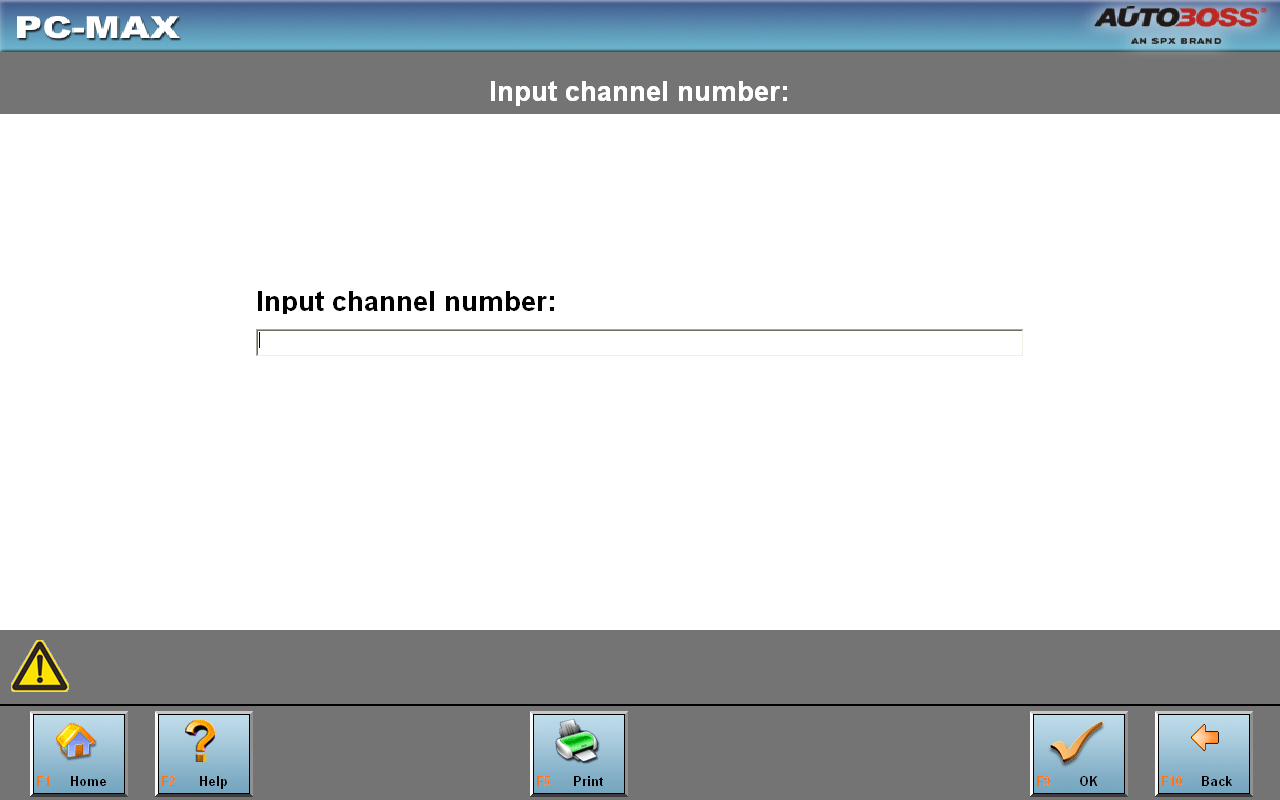
Click on [10-Adaptation] to enter the interface of inputting channel number as shown in left image.
Note:
Self-adaptation includes: self-study during idle, service reset,
IMMO adaptation and so on. You should login first for some of the
functions. For login methods, please refer to
![]() [11-Login procedure] on page 26.
[11-Login procedure] on page 26.
After inputting the relative channel number, click on [OK] to enter the interface as shown in left image.
-
[Input]: Back to the “input channel number” interface;
-
[Read]: Read the adaptation value of current channel;
-
[Back]: Back to function list interface;
-
[Print]: Save the current screen to SD card.
Click on the button [Read] to read the adaptation value of current channel.
-
[Input]: Input new adaptation value;
-
[Back]: Back to function list menu.
-
[Print]: Save the current screen to SD card.
Click on [Input] in enter the “input adaptation value” interface shown on the left. Input the new value and then click the button [Ok] to go to the next step.


After inputting the new value, new adaptation value will be displayed on the screen. If no error is found, please click on the button [Change] to go to the next step.
Last step: Click on the button [Save] to save the new adaptation value and go back to the self-adaptation interface.


![]() [11-Login
procedure]
[11-Login
procedure]
To perform adaptation in some group, login will be needed first. Just click on the button [11-Login procedure], input the code number and then click on [OK].
Note: Login is required when performing functions such as ECU coding, change channel adaptation and IMMO, etc.
![]() [15-Write
VIN]
[15-Write
VIN]
Volkswagen/Audi uses the 3rd generation anti-theft technology, if you change engine control unit and instrument cluster at the same time you must rewrite the VIN code. Please click on [15-Write VIN] to input the new VIN.