

Content
1 Introduction 1
1.1 Function and Feature 1
1.2 Layout of Main Unit 1
1.3 Technical Parameters 2
1.4 Configuration 2
2 Operation 8
2.1 Software installation & cable connection 8
2.1.1 Diagnostic software installation 8
2.1.2 Cable connection 9
2.2 Interface Instruction 11
2.2.1 Starting Interface 11
2.2.2 Diagnostic Program 11
2.2.3 System Setting 12
2.2.4 Self check 13
2.2.5 Version Information 13
2.2.6 Homepage 13
2.2.7 Print 13
2.2.8 Exit 15
2.3 Software update 16
2.3.1 Upgrading Instructions 16
3 Test Procedure 20
3.1 Engine ECU Testing Methods 20
Order Information 28
1 Introduction


1.1 Function and Feature
-
OE level coverage for European, Asian, American and Chinese cars
-
Supports Multi-language
-
Multi-functions
-
Wireless diagnosis operated on PC
-
CAN-BUS with high/low speed
-
One OBDII connector for all CAN bus systems
-
Continuous software update online
-
6-layer electronic circuit board
-
Self-check function
1.2 Layout of Main Unit
The main unit layout is as shown in left picture.
-
PC/laptop (NOT INCLUDED)
-
Wireless adaptor
-
PC-MAX main unit
-
Vehicle (ECU)
-
Main cable port
-
Power indicator
-
Wireless operation indicator
-
USB port
-
Power supply (+12V) port
1.3 Technical Parameters
PC configuration CPU: Pentium 4 (or Celeron R series) or above
Memory: Minimum 256MB
-
Operating system: WINDOWS XP/2000 Power supply: DC 12V, AC 110~250V 50/60Hz;
-
Power: DC 9~15V
-
Wireless working frequency: 2400 MHz-2483.5 MHz. (ISM-Band)
-
Wireless communication distance: around 20~100 Meters (depending on environment)
-
Wireless transfer speed: max. 2Mbps, self-adaptation and power control
-
Memory temperature: -30~90ºC
-
Working temperature: -10~70ºC
-
Humidity: <90%
1.4 Configuration
|
Picture |
Item |
Description |
|
|
Name: PC/laptop Quantity: 1
Note: This is not included in standard configuration. |
Function: Used for wireless diagnosis and display
|
|
|
Name: PC-MAX main unit Quantity: 1 |
Function: Data transfer connecting with vehicle |
|
|
Name: Wireless adaptor Quantity:1 |
Function: Connect to PC/Laptop for wireless data transmission |
|
|
Name: Installation CD Quantity: 1 |
Function: Used to install operating software in PC |
|
|
Name: Main Cable Quantity: 1 |
Function: Connect the main unit and connectors with vehicle |
|
|
Name: BENZ-38 connector Quantity: 1 |
Function: Used for testing Mercedes-Benz vehicles equipped with a circular 38-pin DLC |
|
|
Name: Benz-14 connector Quantity: 1 |
Function: Used for testing Mercedes-Benz sprinter |
|
|
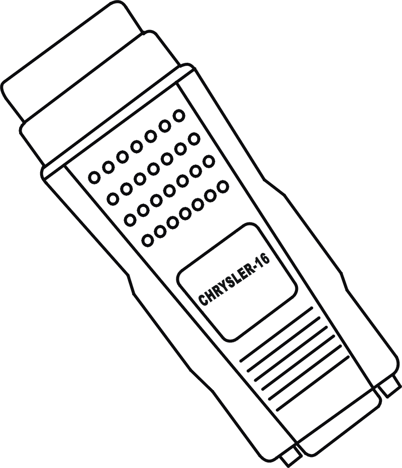
Name: Chrysler-16 connector Quantity: 1
|
Function: Used for testing Chrysler with CCD protocol
Note: Optional adaptor |
|
|
Name: BMW-20 connector Quantity: 1 |
Function: Used for testing BMW vehicles equipped with a 20-pin DLC |
|
|
Name: Chery/Fiat -3 connector Quantity: 1 |
Function: Used for testing Chery/Fiat vehicles equipped with a 3-pin DLC |
|
|
Name: GM-12 connector Quantity: 1 |
Function: Used for testing GM/Daewoo vehicles equipped with a 12-pin DLC |
|
|
Name: Kia-20 connector Quantity: 1 |
Function: Used for testing KIA vehicles equipped with a 20-pin DLC |
|
|
Name: Mazda-17 connector Quantity: 1 |
Function: Used for testing MAZDA vehicles equipped with a 17-pin DLC |
|
|
Name: Toyota-17 connector Quantity: 1 |
Function: Used for testing Toyota/Lexus vehicles equipped with a semi-circular 17pin DLC |
|
|
Name: Toyota-22 connector Quantity: 1 |
Function: Used for testing Toyota/Lexus vehicles with a rectangular 22-pin DLC |
|
|
Name: MIT-12+16 connector Quantity: 1 |
Function: Used for testing Mitsubishi and Hyundai vehicles equipped with a 12-pin or 16-pin DLC |
|
|
Name: Honda-3 connector Quantity: 1 |
Function: Used for testing HONDA and ACURA vehicles equipped with a 3-pin DLC |
|
|
Name: Benz-4 connector Quantity: 1 |
Function: Used for testing Mercedes-Benz before 1997 with flash codes, which are usually equipped with either a rectangular 8-pin or 16-pin DLC |
|
|
Name: Audi-4 connector Quantity: 1 |
Function: Used for testing VW/Audi vehicles with a 4-pin (2x2) DLC |
|
|
Name: Nissan-14 connector Quantity: 1 |
Function: Used for testing Nissan and Infiniti vehicles equipped with a 14-pin DLC |
|
|
Name: OBD-16 connector Quantity: 1 |
Function: Used for testing all vehicles compliant with OBDII, EOBD and J1962 with 16-pin DLC |
|
|
Name: Citroen-16C connector Quantity: 1 |
Function: Used for testing Citroen vehicles equipped with a 16-pin DLC |
|
|
Name: Jumper Quantity: 1 |
Function: Short circuit test for flash code reading |
|
|
Name: Battery power cable Quantity: 1 |
Function: Gains power supply from battery |
|
|
Name: Cigarette lighter power cable Quantity: 1 |
Function: Gains power supply via cigarette lighter on car |
|
|
Name: DC adaptor Quantity: 1 |
Function: Used to connect with power supply of 12V DC voltage |
|
|
Fuse 5A 30*6 |
Function: Spare parts |
|
Fuse 5A 20*5 |
Function: Spare parts |


NOTE: Configuration varies as per software package. For complete configuration, please refer to the relevant shipping list.