- •Graphical calculation work
- •Variant 1
- •1. Introduction
- •2. Short description of the design and operation of fuel system Tу-154 and its elements
- •3. Block diagram of the system
- •Figure 3 Structural block diagram of the fuel system
- •Figure 4 Structural (detailed) scheme of fuel system
- •4. Tree of events for r2 situation
- •5. Calculation of non failure operation indices of system and its elements
- •6. Algorithm development for detection of problem with functional system of the aircraft
National Aviation University
Aerospace Institute
Aircraft Faculty
Aircraft Airworthiness Retaining Department

Graphical calculation work
on the subject
“MAINTAINING THE AIRWORTHINESS OF THE AIRCRAFT”
on theme
«Analysis of failures and damage to structural elements of the fuel system Tу-154 search algorithm development and their causes»
Variant 1
Mark:____________________
Date:____________________
Signature:_________________
Made by Suprunets M.V.
Group 505-2 FLA
Checked by Goncharenko A.V
Kiev 2015
Contents
|
1. Introduction ……………………………………………………………... |
3 |
|
2. Short description of the design and operation of fuel system Tу-154 and its elements………………………………………………………………… |
3 |
|
3. Block diagram of the system……………………………………………. |
6 |
|
4. Tree of events for R2 situation…………………………………………… |
7 |
|
5. Calculation of non failure operation indices of system and its elements... |
8 |
|
6. Algorithm development for detection of problem with functional system of the aircraft……………………………………………………………….. |
9 |
|
Conclusion………………………………………………………………….. |
11 |
|
Reference…………………………………………………………………… |
12 |
1. Introduction
By itself the graphical calculation work shows designing of separate elements of the maintenance (M) system of aviation technique on the basis of their faultlessness and operational manufacturability analysis.
An explanatory note for the term paper consists of such sections:
short description of the given system with the principle system;
structural and functional analysis of the system;
calculation faultlessness indexes of the system and its elements;
systematization and classification of the most probable refusals and failures of functional system elements;
operability analysis of the system with refusals or failures of its separate elements;
algorithm development for maintenance personnel actions relatively to the reasons of failures searching of given aircraft functional system.
Properly made structural system and logic-functional analysis of a given system gives a possibility for performing the qualitative faultlessness and operational manufacturability analysis.
2. Short description of the design and operation of fuel system Tу-154 and its elements
Aircraft fuel system is designed to accommodate and store flight performance required for fuel supply and supplying it to the engine running in the required amount and the desired pressure in all flight modes.
The fuel system is divided into two systems: the outer, or aircraft, and internal or engine systems. Internal systems are fuel assemblies and interconnecting piping installed on the engine and supplied with the engine НК-8-2У (НК-8-2).
Aircraft fuel system consists of fuel tanks and the following systems: fuel supply main engines, fuel supply of the engine auxiliary power unit, fuel transfer, drain the fuel tanks, refueling, as well as the automation system flow rate and measurement of fuel ATST6 (АЦТ6), measurement of fuel consumption SIRT-1T (СИРТ-1Т). Later on the aircraft instead of ATST6 system will be installed automatic flow measurement and fuel SUIT4-1T (СУИТ4-1Т). On airplanes, the latest release in the aircraft fuel system is included in the fuel supply system deicing fluid
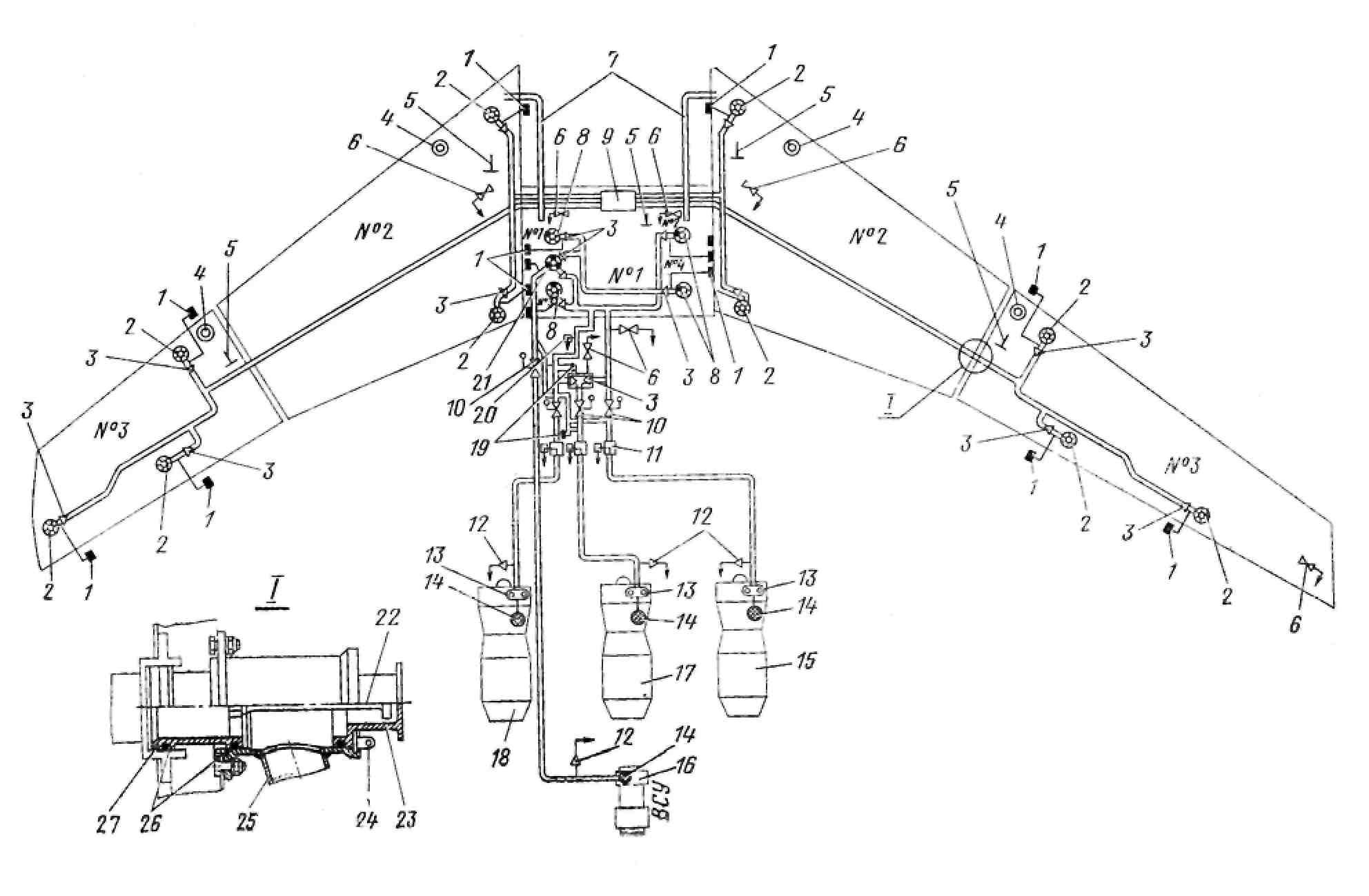
Fuel placed on the plane in the five integral fuel tank. Three tank - a tank №1 and № 2 two tank (Figure 1) - located in the center section and two tanks (tanks №3) - in the detachable parts of the wing. On airplanes, the latest release of space in the center section between the side ribs №3 and first and second side members is used as a tank №4. This tank will initially ballast, and in subsequent versions of the aircraft fuel will be supplied from a tank №1. Tank №4, being ballast, aggregates and has elements of all systems required for its normal functioning.
Power engines is carried out from the supply tank №1, which is replenished from the fuel tank №2 and 3, and in the future - from the tank №4
Centralized filling tanks with fuel produced from below, through the two receiving mouth set in a sock center-right wing. In case of refusal of centralized fueling pressure filling of tanks (except consumables) can be made through the upper tank filling mouth
Gauges of the fuel system and controls its
operation are located on the remote flight engineer on the panel of
the fuel system and start the APU, the instrument panel controls of
the engines on the switchboard panel flight engineer, as well as on
the dashboard dressings, located under the hatch on the bottom
surface of the sock center-right wing.Each fuel tank is a sealed
chamber formed by spars, ribs and upper and lower wing panels.
1 — pressure alarm СДУ2А-0Л8 и СДУ2-0,18; 2 — pump ЭЦН-323;
3 — check valve; 4 — filler neck; 5 — magnetic line;
6 — drain valve; 7 — overflow pipe; 8 — pump ЭЦН-325;
9 — porcioner; 10 — shut off valve; 11 — fuel flow transmitter ДРТМС-ША;
12 — fitting conservation 1703А-Т; 13 — booster pump ДЦН-44Т;
14 — filter; 15 — engine № 3;16 — engine APU;
17 — engine № 2; 18 — engine № 1; 19 — temperature and pressure relief valve;
30 — density sensor ДПЕ5-1; 21 — pump ЭЦН-319;
22 — rod; 23 — cap; 24 — retaining ring, 25 — pipeline;26 — sealing;
27 — adapter.
Figure 1 Schematic diagram of the fuel system
