

Advanced_Renderman_Book[torrents.ru]
.pdf9.2 Reflections
We can partially overcome this difficulty with the following strategy:
1.We assume that the environment map exists on the interior of a sphere with a finite and known radius as well as a known center. Example: if the environment map is of a room interior, we choose a sphere radius representative of the room size. (Even if we have assembled an environment map from six rectangular faces, because it is indexed by direction only, for simplicity we can just as easily think of it as a spherical map.)
2.Instead of indexing the environment by direction only, we define a ray using the position and mirror direction of the point, then calculate the intersection of this ray with our aforementioned environment sphere.
3.The intersection with the environment sphere is then used as the environment lookup direction.
Thus, if a simple environment( ) lookup is like ray tracing against a sphere of infinite radius, then the scheme above is simply ray tracing against a sphere of a radius appropriate to the actual scene in the environment map.
As a subproblem, we must be able to intersect an environment sphere with a ray. A general treatment of ray/object intersections can be found in (Glassner, 1989), but the ray/sphere case is particularly simple. If a ray if described by end point E and unit direction vector 1 (expressed in the coordinate system of a sphere centered at its local origin and with radius r), then any point along the ray can be described as E + It (for free parameter t). This ray intersects the sphere anyplace that  Because the length of a vector is the square root of its dot product with itself, then
Expanding the x, y, and z components for the dot product calculation yields
for which the value(s) of t can be solved using the quadratic equation. This solution is performed by the raysphere function, which in turn is used by our enhanced Environment routine (see Listing 9.5). Note that Environment also returns an alpha value from the environment map, allowing us to composite multiple environment maps together.
9.2.2 Creating Cube Face Environment Maps
The creation of cube face environment maps is straightforward. First, six reflection images are created by rendering the scene from the point of view of the reflective object in each of six orthogonal directions in "world" space, given in Table 9.1.
9 Illumination Models and Lights |
215 |
|
Listing 9.5 Environment function replaces a simple environment call, giving more accurate reflections by tracing against an environment sphere of finite radius.
/* raysphere - calculate the intersection of ray (E,I) with a sphere
*centered at the origin and with radius r. We return the number of
*intersections found (0, 1, or 2), and place the distances to the
*intersections in t0, tl (always with t0 <= tl). Ignore any hits
*closer than eps.
*/
float |
|
raysphere (point E; vector I; |
/* Origin and unit direction of the ray */ |
float r; |
/* radius of sphere */ |
float eps; |
/* epsilon - ignore closer hits */ |
output float t0, t1; |
/* distances to intersection */ |
) |
|
{
/* Set up a quadratic equation -- note that a==1 if I is normalized */
float b = 2 * ((vector E) . I);
float c = ((vector E) . (vector E)) - r*r;
float discrim = b*b - 4*c; |
|
float solutions; |
|
if (discrim > 0) { |
/* Two solutions */ |
discrim = sqrt(discrim); t0 = (-discrim - b) / 2; if (t0 > eps) {
t1 = (discrim - b) / 2; solutions = 2;
} else {
t0 = (discrim - b) / 2; solutions = (t0 > eps) ? 1 : 0;
}
}else if (discrim == 0) { /* One solution on the edge! */ t0 = -b/2;
solutions = (t0 > eps) ? 1
} else { /* imaginary solution -> no intersection */ solutions = 0;
}
return solutions;
}
/* Environment() - A replacement for ordinary environment() lookups, this
*function ray traces against an environment sphere of known, finite radius.
*Inputs are:
*envname - filename of environment map
*envspace - name of space
*environment map was made in
*envrad - approximate supposed radius of environment
*sphere P, R - position and direction of traced ray
*blur - amount of additional blur to add to environment map
*Outputs are: return value - the color of
*incoming environment light
*alpha - opacity of environment map lookup in the direction R.
9.2Reflections
*Warning - the environment call itself takes derivatives, causing
*trouble if called inside a loop or varying conditional! Be cautious.
*/
color Environment ( string envname, envspace; uniform float envrad; point P; vector R; float blur; output float alpha;)
{
/* Transform to the space of the environment map */ point Psp = transform (envspace, P);
vector Rsp = normalize (vtransform (envspace, R)); uniform float r2 = envrad * envrad;
/* Clamp the position to be *inside* the environment sphere */ if ((vector Psp).(vector Psp) > r2)
Psp = point (envrad * normalize (vector Psp)); float t0, tl;
if (raysphere (Psp, Rsp, envrad, 1.Oe-4, t0, t1) > 0) Rsp = vector (Psp + t0 * Rsp);
alpha = float environment (envname[3], Rsp, "blur", blur, "fill", 1); return color environment (envname, Rsp, "blur", blur);
}
Table 9.1: The six view directions in an environment map.
Face view |
Axis toward top |
Axis toward right |
px (positive x) |
+y |
-z |
nx (negative x) . |
+y |
+z |
py |
-z |
+x |
ny |
+z |
+x |
pz |
+y |
+x |
nz |
+y, |
-x |
Next, these six views (which should be rendered completely cover all directions) are combined into a done from the RIB file:
using a square 90° field of view to single environment map. This can be
MakeCubeFaceEnvironment px nx py ny pz nz envfile
Here px, nx, and so on are the names of the files containing the individual face images, and envfile is the name of the file where you would like the final environment map to be placed.
Alternatively, most renderers will have a separate program that will assemble an environment map from the six individual views. In the case of PRMan, this can be done with the txmake program:
txmake -envcube px nx py ny pz nz envfile
216 9 Illumination Models and Lights
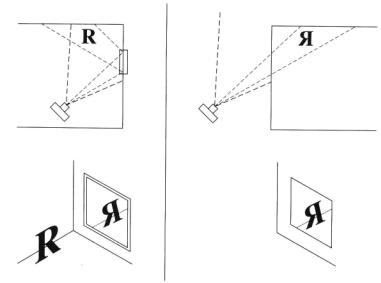
Figure 9.4 Creating a mirrored scene for generating a reflection map. On the top left, a camera views a scene that includes a mirror. Below is the image it produces. On the top right, the camera instead views the mirror scene. Notice that the image it produces (below) contains the required reflection.
9.2.3 Flat Surface Reflection Maps
For the special case of flat objects (such as floors or flat mirrors), there is an even easier and more efficient method for producing reflections, which also solves the problem of environment maps being inaccurate for flat objects.
For the example of a flat mirror, we can observe that the image in the reflection would be identical to the image that you would get if you put another copy of the room on the other side of the mirror, reflected about the plane of the mirror. This geometric principle is illustrated in Figure 9.4.
Once we create this reflection map, we can turn it into a texture and index it from our shader. Because the pixels in the reflection map correspond exactly to the reflected image in the same pixels of the main image, we access the texture map by the texture's pixel coordinates, not the s, t coordinates of the mirror. We can do this by projecting P into "NDC" space. This is done in the ReflMap function in Listing 9.6.
9.2.4 General Reflections and Shiny Surfaces
We would prefer to write our shaders so that we may use either reflection or environment maps. Therefore, we can combine both into a single routine, SampleEnvironment(), given in Listing 9.7.

217
9.2 Reflections
Listing 9.6 ReflMap function performs simple reflection mapping. color ReflMap ( string reflname; point P; float blur;
output float alpha; )
{
/* Transform to the space of the environment map */ point Pndc = transform ("NDC", P);
float x = xcomp(Pndc), y = ycomp(Pndc);
alpha = float texture (reflname[3], x, y, "blur", blur, "fill", 1); return color texture (reflname, x, y, "blur", blur);
}
function makes calls to either or both of
Environment or ReflMap as needed.
#define ENVPARAMS envname, envspace, envrad #define DECLARE_ENVPARAMS
string envname, envspace; #define DECLARE_DEFAULTED_ENVPARAMS
string envname = " ", envspace = "world"; uniform float envrad = 100
color
Sample Environment (point P; vector R; float Kr, blur; DECLARE_ENVPARAMS;)
{
color C = 0; float alpha;
if (envname !- " ") {
if (envspace == "NDC")
C = ReflMap (envname, P, blur, alpha);
else C = Environment (envname, envspace, envrad, P, R, blur, alpha);
}
return Kr*C;
}
A few comments on the source code in Listing 9.7. To allow easy specification of the many environment-related parameters, we define macros ENVPARAMS, DECLARE_ENVPARAMS, and DECLARE_DEFAULTED_ENVPARAMS, which are macros containing the parameter names, declarations, and declarations with default values, respectively. These macros allow us to succinctly include them in any shader, as we have done in shader shinymetal (Listing 9.8).
218 9 Illumination Models and Lights
Listing 9.8 MaterialShinyMetal and the shinymetal shader.
/ * Compute the color of the surface using a simple metal-like BRDF. To give a
*metallic appearance, both diffuse and specular components are scaled by the color
*of the metal. It is recommended that Kd < 0.1, Ks > 0.5, and roughness > 0.15 to
*give a believable metallic appearance
*/
color MaterialShinyMetal (normal Nf; color basecolor;
float Ka, Kd, Ks, roughness, Kr, blur; DECLARE_ENVPARAMS;)
{
extern point P; extern vector I;
vector IN = normalize(I), V = -IN; vector R = reflect (IN, Nf);
return basecolor * (Ka*ambient() + Kd*diffuse(Nf) + Ks*specular(Nf,V,roughness) + SampleEnvironment (P, R, Kr, blur, ENVPARAMS));
}
surface
shinymetal ( float Ka = 1, Kd = 0.1, Ks = 1, roughness = 0.2;
float Kr = 0.8, blur = 0; DECLARE_DEFAULTED_ENVPARAMS;
{
normal Nf = faceforward (normalize(N), I);
Ci = Material5hinyMetal (Nf, Cs, Ka, Kd, Ks, roughness, Kr, blur, ENVPARAMS); Oi = Os; Ci *= Oi;
}
With this routine in our toolbox, we can make a straightforward shader that can be used for shiny metals like mirrors, chrome, or copper (see Listing 9.8). If you are using the shader for a flat object with a prepared flat reflection map, you need only pass "NDC" as the envspace parameter and the SampleEnvironment function will correctly access your reflection map.
9.2.5Fresnel and Shiny Plastic
All materials are more reflective at glancing angles than face-on (in fact, materials approach 100% reflectivity at grazing angles). For polished metals, the face-on reflectivity is so high that this difference in reflectivity with angle is not very noticeable. You can convince yourself of this by examining an ordinary mirror-it appears nearly equally shiny when you view your reflection head-on versus when you look at the mirror at an angle. So we tend to ignore the angular effect on reflectivity, assuming for simplicity that polished metals are equally reflective in all directions (as we have in the previous section).

219
9.2 Reflections
Figure 9.5 The ratio of reflected to transmitted light at a material boundary changes with the angle of the incident light ray.
Dielectrics such as plastic, ceramics, and glass are much less reflective than metals overall, and especially so when viewed face-on. Therefore, their higher reflectivity at grazing angles is a much more significant visual detail (see Figure 9.5). The formulas that relate angle to reflectivity of such materials .are known as the Fresnel equations.
A function that calculates the Fresnel terms is included in Shading Language:
void fresnel (vector I; normal N; float eta;
output float Kr, Kt; output vector R, T);
According to Snell's law and the Fresnel equations, fresnel computes the reflection and transmission direction vectors R and T, respectively, as well as the scaling factors for reflected and transmitted light, Kr and Kt. The I parameter is the normalized incident ray, N is the normalized surface normal, and eta is the ratio of refractive index of the medium containing I to that on the opposite side of the surface.
We can use fresnel ( ) to attenuate the relative contributions of environmental and diffuse reflectances. This is demonstrated in the MaterialShinyPlastic and shinyplastic, both shown in Listing 9.9. Figure 9.6 compares the appearance of MaterialShinyMetal
and MaterialShinyPlastic.
The index of refraction of air is very close to 1.0, water is 1.33, ordinary window glass is approximately 1.5, and most plastics are close to this value. In computer graphics, we typically assume that 1.5 is a reasonable refractive index for a very wide range of plastics and glasses. Therefore, a reasonable value for the eta parameter passed to fresnel ( ) is 1/1.5. Nearly any optics textbook will list the indices of refraction for a variety of real materials, should you wish to be more physically accurate.
Of course, for real materials the refractive index is wavelength dependent. We tend to ignore this effect, since we have such an ad hoc approach to spectral sampling and color spaces anyway. Although metals also have wavelength-dependent indices of refraction, Fresnel effects, and angle-dependent spectral reflectivities, they are much less visually noticeable in most metals, so we usually just pretend

220 9 Illumination Models and Lights
Listing 9.9 shinyplastic shader is for highly polished plastic and uses so that reflections are stronger at grazing angles.
color
MaterialShinyPlastic ( normal Nf; color basecolor;
float Ka, Kd, Ks, roughness, Kr, blur, ior; DECLARE_ENVPARAMS;)
{
extern vector I; extern point P; vector IN = normalize(I), V = -IN; float fkr, fkt; vector R, T; fresnel (IN, Nf, 1/ior, fkr, R, T); fkt = 1-fkr;
return fkt * basecolor * (Ka*ambient() + Kd*diffuse(Nf))
+(Ks*fkr) -° specular(Nf,V,roughness)
+SampleEnvironment (P, R, fkr*Kr, blur, ENVPARAMS));
}
surface
shinyplastic ( float Ka = 1, Kd = 0.5, Ks = .5, roughness = 0.1; float Kr = 1, blur = 0, for = 1.5; DECLARE_DEFAULTED_ENVPARAMS; )
{
normal Nf = faceforward (normalize(N), I);
Ci = MaterialShinyPlastic |
(Nf, Cs, Ka, Kd, Ks, roughness, Kr, |
|
blur, ior, ENVPARAMS); |
Oi = Os; Ci *= Oi; |
|
}
Figure 9.6 MaterialShinyMetal (left) and MaterialShinyPlastic (right). See also color plate 9.6.
221
9.3Illuminance Loops, or How diffuse( ) and specular( ) Work
that shiny metals reflect uniformly. You are, of course, perfectly free to go to the extra effort of computing the wavelength and angle dependency of metals!
Important note: in MaterialShinyPlastic we set fkt=l-fkr, overriding the value
returned by fresnel( ). The easons for this are extremely subtle and well beyond the scope of this book. Suffice it to say that the value that fresnel( ) is supposed to return for Kt assumes a more rigorous simulation of light propagation than either PRMan or BMRT provides. In light of these inaccuracies, the intuitive notion that Kt and Kr ought to sum to 1 is about as good an approximation as you might hope for. We will therefore continue to use this oversimplification.
9.3Illuminance Loops, or How diffuse and specular( ) Work
We have seen classes of materials that can be described by various relative weightings and uses of the built-in diffuse( ) and specular( ) functions. In point of fact, these are just examples of possible illumination models, and it is quite useful to write alternative ones. In order to do that, however, the shader needs access to the lights: how many are there, where are they, and how bright are they?
The key to such functionality is a special syntactic structure in Shading Language
called an illuminance loop:
illuminance ( point position ) { statements;
}
illuminance ( point position; vector axis; float angle ) { statements;
}
The illuminance statement loops over all light sources visible from a particular position. In the first form, all lights are considered, and in the second form, only those lights whose directions are within angle of axis (typically, angle=π/2 and axis=N, which indicates that all light sources in the visible hemisphere from P should be considered). For each light source, the statements are executed, during which two additional variables are defined: L is the vector that points to the light source, and Cl is the color representing the incoming energy from that light source.
Perhaps the most straightforward example of the use of illuminance loops is the implementation of the diffuse( ) function:
color diffuse (normal Nn)
{
extern point P; color C = 0;
illuminance (P, Nn, PI/2) {
222 9 Illumination Models and Lights
C += Cl * (Nn . normalize(L));
}
return C;
}
Briefly, this function is looping over all light sources. Each light's contribution is computed using a Lambertian shading model; that is, the light reflected diffusely is the light arriving from the source multiplied by the dot product of the normal with the direction of the light. The contributions of all lights are summed and that sum is returned as the result of diffuse( ).
9.4Identifying Lights with Special Properties
In reality, surfaces simply scatter light. The scattering function, or BRDF (which stands for bidirectional reflection distribution function) may be quite complex. Dividing the scattering function into diffuse versus specular, or considering the BRDF to be a weighted sum of the two, is simply a convenient oversimplification. Many other simplifications and abstractions are possible.
In the physical world, light scattering is a property of the surface material, not a property of the light itself or of its source. Nonetheless, in computer graphics it is often convenient and desirable to place light sources whose purpose is solely to provide a highlight, or alternatively to provide a soft fill light where specular highlights would be undesirable. Therefore, we would like to construct our diffuse( ) function so that it can ignore light sources that have been tagged as being "nondiffuse"; that is, the source itself should only contribute specular highlights. We can do this by exploiting the message passing mechanism of Shading Language, wherein the surface shader may peek at the parameters of the light shader.
float lightsource ( string paramname; output type result )
The lightsource( ) function, which may only be called from within an illuminance loop, searches for a parameter of the light source named paramname. If such a parameter is found and if its type matches that of the variable result, then its value will be stored in the result and the lightsource( ) function will return 1.0. If no such parameter is found, the variable result will be unchanged and the return value of lightsource will be zero.
We can use this mechanism as follows. Let us assume rather arbitrarily that any light that we wish to contribute only to specular highlights (and that therefore should be ignored by the diffuse( ) function) will contain in its parameter list an output float parameter named nondiffuse. Similarly, we can use an output float parameter named __nonspecular to indicate that a particular light should not contribute to specular highlights. Then implementations of diffuse( ) and specular( ), as shown in Listing 9.10, would respond properly to these controls.