

Advanced_Renderman_Book[torrents.ru]
.pdf6.5Rendering Artifacts
6.5.1Eye Splits
Sometimes PhotoRealistic RenderMan will print the error message "Cannot split primitive at eye plane," usually after appearing to stall for quite a while. This error message is a result of perhaps the worst single algorithmic limitation of the modified REYES algorithm: in order to correctly estimate the shading rate required for a primitive, the primitive must first be projected into raster space in order to evaluate its size. Additionally, recall that the first step in the geometric pipeline is to bound the primitive and sort it into buckets based on its position in raster space, which requires the same projection. The problem is that the mathematics of perspective projection only works for positions that are in front of the camera. It is not possible to project points that are behind the camera. For this reason, the renderer must divide the primitive into areas that are in front of and areas that are behind the camera.
Most rendering algorithms, if they require this projection at all, would clip the primitive against the near clipping plane (hence the name) and throw away the bad regions. However, the entire REYES geometric and shading pipelines require subprimitives that are rectangular in parametric space, which can be split and diced cleanly. Clipping does not create such primitives and cannot be used. Instead, REYES simply splits the primitive hoping that portions of the smaller subprimitives will be easier to classify and resolve.
Figure 6.5 shows the situation. Notice that primitives that lie entirely forward of the eye plane are projectable, so can be accepted. Primitives that lie entirely behind the near clipping plane can be trivially culled. It is only primitives that span both planes that cannot be classified and are split. The region between the planes can be called the "safety zone." If a split line lies entirely within this zone (in 3D, of course), both children of the bad primitive are classifiable, which is the situation we are hoping for. If the split line straddles a plane, at least we will shave some of the bad primitive away and the remaining job, we hope, is slightly easier. REYES splits as smartly as it can, attempting to classify subprimitives.
Unhappily, there are geometric situations where the splitting simply doesn't work in a reasonable number of steps. "Reasonable" is defined as a small integer because each split doubles the number of subprimitives, so even 10 attempts create 2^10 = 1024 primitives. If, after splitting the maximum permitted number of times, the primitive still cannot be classified, REYES gives up and throws the primitive away and prints the "Cannot split" message. If that primitive was supposed to be visible, the lost section will leave a hole in the image.
Primitives that have large displacement bounds, or are moving rapidly toward the camera, will exacerbate the eye-splitting problem because the parametric splitting process will do very little to reduce the bounding box. Indeed, for primitives for which the camera is inside the displacement bound of part of the surface, or primitives whose motion path actually goes through the camera, splitting can never succeed.
In order to reduce the artifacts due to eye-split culling, the key is to give the renderer the largest possible safety zone. Place the near clipping plane as far forward

152 6 How PhotoRealistic RenderMan Works
Figure 6.5 The geometric relationship of the near and eye planes gives rise to three categories of primitives: the cullable, the projectable, and the "spanners," which require splitting.
as is possible without otherwise affecting the image. The near clipping plane can be placed surprisingly far forward for most shots made with cameras that have reasonable fields of view. If you don't normally set the clipping plane, set it to some small but reasonable value immediately-the default value of 1e-10 is just about as bad as you could get! The number of splitting iterations that will be permitted can be controlled with a rendering option, and if you permit a few more, you can sometimes help handling of large but otherwise simple primitives. Beware, however, of the displacement and motion cases, because upping the limit will just let the renderer waste exponentially more time before it gives up.
Also, make sure that displacement bounds for primitives near the camera (for example, the ground plane) are as tight as possible and that the shader is coded so that the displacement itself is as small as possible. If you place the camera so close to some primitive that the displacement bound is a significant portion of the image size, there will be no end of trouble with both eye splits and displacement stretching (discussed later). In flyovers of the Grand Canyon, the canyon should be modeled, not implemented as a displacement map of a flat plane!
It will also help to keep the camera as high off the ground as possible without ruining the composition of the shot. REYES simply has lots of trouble with worm'seye views. And make sure that no object is flying through the camera (you wouldn't do that in live-action photography, would you?). Generally, if you pretend that the CG camera has a physical lens that keeps objects in the scene at least a certain distance away and respect that border, you will have fewer problems with eye splits.

153
6.5 Rendering Artifacts
Figure 6.6 Tessellation differences result in patch cracks, but these can be repaired by moving binary-diced vertices.
6.5.2Patch Cracks
Patch cracks are tiny holes in the surface of objects that are caused by various errors in the approximation of primitives by their tessellations (we'll use the term loosely to include tessellation-created cracks on primitives other than patches). Patch cracks usually appear as scattered pinholes in the surface, although they can sometimes appear as lines of pinholes or as small slits. Importantly, they always appear along parametric lines of primitives. They are recognizably different from other holes created by clipping, culling, or bucketing errors, which are usually larger, often triangular, and occur in view-dependent places (like on silhouettes or aligned with bucket boundaries).
Patch cracks occur because when objects are defined by sets of individual primitives, the connectedness of those primitives is only implied by the fact that they abut, that they have edges that have vertices in common. There is no way in the RenderMan Interface to explicitly state that separate primitives have edges that should be "glued together." Therefore, as the primitives go through the geometric pipeline independently, there is a chance that the mathematical operations that occur on one version of the edge will deviate from those on the other version of the edge, and the vertices will diverge. If they do, a crack occurs between them.
The deviations can happen in several ways. One is the tessellation of the edge by adjacent grids being done with micropolygons of different sizes. Figure 6.6 shows that such tessellations naturally create intermediate grid vertices that do not match, and there are tiny holes between the grids. For many years, PRMan has had a switch that eliminated most occurrences of this type of crack. Known as binary dicing, it requires that every grid have tessellations that create a power-of-two number of micropolygons along each edge. Although these micropolygons are smaller than are required by shading rate alone, binary dicing ensures that adjacent grids have tessellations that are powers-of-two multiples of each other (generally, a single factor of two). Thus, alternating vertices will coincide, and the extra vertices on one side are easily found and "pasted" to the other surface.
Another way that patch cracks can happen is when the displacement shader that operates on grid vertices gets different results on one grid from another. If a common vertex displaces differently on two grids, the displacement literally rips
154 6 How PhotoRealistic RenderMan Works
the surface apart, leaving a crack between. One common reason for such differing results is displacement mapping using texture filter sizes that are mismatched (see Section 6.5.4). The texture call then returns a slightly different value on the two grids, and one grid displaces to a different height than the other. Another common reason is displacement occurring along slightly different vectors. For example, the results of calculatenormal are almost guaranteed to be different on the left edge of one grid and on the right edge of the adjacent grid. If displacement occurs along these differing vectors, the vertices will obviously go to different places, opening a crack. Unfortunately, only careful coding of displacement shaders can eliminate this type of cracking.
Notice that patch cracks cannot happen on the interiors of grids. Because grid micropolygons explicitly share vertices, it is not possible for such neighbor micropolygons to have cracks between them. For this reason, patch cracks will only occur along boundaries of grids, and therefore along parametric edges. In PRMan versions prior to 3.9, patch cracks could occur on any grid edge, including those that resulted from splitting a patch into subpatches. Later versions of PRMan have a crack-avoidance algorithm that glues all such subpatches together. Therefore, modern versions of PRMan will only exhibit patch cracks along boundaries of original primitives, not along arbitrary grid boundaries.
6.5.3Displacement Stretching
Another problem that displacement shaders might create is stretching of micropolygons. This is caused when displacement shaders move the vertices of a micropolygon apart, so that it no longer obeys the constraint that it is approximately the size specified by the shading rate.
In the process of dicing, the renderer estimates the size of the primitive onscreen and makes a grid that has micropolygons that approximately match the shading rate. Shading then occurs on the vertices of the grid (the corners of the micropolygons). Displacement shaders are permitted to move grid vertices, but there is no constraint on where they are moved. If two adjacent grid vertices are moved in different directions (wildly or subtly), the area of the micropolygon connecting them will change. Generally, this change is so small that the micropolygon is still safely in the range expected of shading rate. However, if the displacement function has strong high frequencies, adjacent grid vertices might move quite differently. For example, an embossing shader might leave some vertices alone while moving vertices inside the embossed figure quite a distance. The micropolygons whose corners move very differently will change size radically, and sometimes will be badly bent or twisted (see Figure 6.7).
Twisted micropolygons have unusual normal vectors, and this alone may be enough to cause shading artifacts. For example, highly specular surfaces are very sensitive to normal vector orientation, so a micropolygon that is twisted in an unusual direction may catch an unexpected highlight.

155
6.5 Rendering Artifacts
Figure 6.7 Displacement stretching leads to micropolygons that are bent, twisted, or significantly larger than anticipated.
More common, however, is that the stretching of the micropolygons will itself be visible in the final image. An individual flat-shaded micropolygon creates a constant-colored region in the image. With a standard shading rate of around a pixel, every pixel gets a different micropolygon and the flat shading is not visible. But large stretched or long twisted micropolygons will cover many pixels, and the constant-colored region will be evident. Sometimes this takes the form of alternating dark and light triangles along the face of a displacement "cliff." Corners of micropolygons that are shaded for the top of the plateau hang down, while corners of micropolygons that are shaded for the valley poke up, interleaved like teeth of a gear.
The visual artifacts of these problems can be somewhat ameliorated by using smooth shading interpolation, which will blur the shading discontinuities caused by the varying normals. However, the geometric problems remain. The primary solution is to lower the frequency content of the displacement shader so that adjacent micropolygons cannot have such wildly varying motion (see Chapter 11 on antialiasing shaders for hints). If this cannot be done, the brute-force approach is to reduce the shading rate to values such as 0.25 pixels or smaller so that even stretched micropolygons stay under one pixel in size. However, this will have significant performance impact, because shading time is inversely proportional to shading rate. Fortunately, shading rate is an attribute of individual primitives, so the extra expense can be limited to the part of the model that requires it.
6.5.4Texture Filter Mismatches
As primitives are split, their subprimitives proceed through the rendering pipeline independently, and when the time comes to dice them, their own individual size on-screen determines the tessellation rate. As a result, it is often the case that the adjacent grids resulting from adjacent subprimitives will project to different

6 How PhotoRealistic RenderMan Works
sizes on the screen and as a result will tessellate at different rates during dicing. Tessellated micropolygons are rectangular in the parametric space of the original primitive, and all of the micropolygons in a single grid will be the same size in that parametric space, but due to the differing tessellation rates, the micropolygons that make up the adjacent grids will have different sizes in parametric space.
One of the artifacts that results from this difference is that filtering calculations based on parametric size will change discontinuously across a grid boundary. In Chapter 11 on shader antialiasing, various filtering techniques are discussed that use parametric size as part of the calculation of filter width. This type of size discontinuity will result in filtering discontinuities, which can be visible in the final image. For example, in simple texturing, the texture filter size defaults to the micropolygon size. The resulting texture can have visible changes in sharpness over the surface of an otherwise smooth primitive. If the result of a texture call is used as a displacement magnitude, a displacement crack can result (Section 6.5.2).
Recent versions of PRMan have significantly reduced problems such as these by the introduction of smooth derivatives. The derivatives and the parametric size values that are available to shaders now describe a smoothly varying idealized parametric size for the micropolygon. That is, the values do not exactly match the true size of the micropolygon in parametric space, but instead track closely the desired parametric size given the shading rate requested (in some sense compensating for the compromises that needed to be made to accommodate binary dicing or other tessellation constraints at the time of dicing). These smoothly varying parametric size estimates ameliorate texture filter size mismatches, both in built-in shading functions and in antialiased procedural textures. Generally, the fact that micropolygons are not exactly the size that they advertise is a small issue, and where it is an issue, it can be compensated for by minor modifications to the shader.
6.5.5Conclusion
The REYES rendering architecture is so general and flexible that new primitives, new graphics algorithms, and new effects features have been added modularly to the existing structure almost continously for over 15 years. The system has evolved from an experimental testbed with a seemingly unattainable dream of handling tens of thousands of primitives into a robust production system that regularly handles images a hundred times more complex than that. The speed and memory enhancements that have been added may appear to have been short-term requirements, as Moore's law allows us to run the program on computers that are faster and have more memory without any additional programming. However, this is shortsighted, for our appetite for complexity has scaled, too, as fast or faster than Moore's law allows. Undoubtedly, in 15 more years, when computers with a terabyte of main memory are common and optical processors chew up 1 billion primitives without flinching, we will still be using the REYES architecture to compute our holofilms.


Introduction to
Shading Language
This chapter provides a refresher on the RenderMan Shading Language. However, it is not a tutorial on programming in general, nor is it intended to be a substitute for The RenderMan Companion or the RenderMan Interface Specification. But rather it is meant to serve as a handy quick reference guide to Shading Language itself.
Shading Language is loosely based on the C programming language. We will use this to our advantage in this chapter by assuming that (1) you already know about general programming concepts such as variables, loops, and so on; (2) you are reasonably familiar with C; (3) your mathematical background is sufficient to allow casual discussion of trigonometry and vector algebra; (4) you have sufficient background in computer graphics to understand intermediate-level concepts related to illumination computations. If you are lacking in any of these areas, you should review the material in Chapter 2 and its references.
160 7 Introduction to Shading Language
7.1 Shader Philosophy
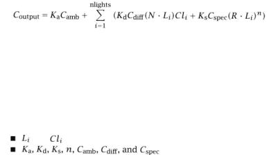
Many renderers have a fixed shading model. This means that a single equation is used to determine the appearance of surfaces and the way that they respond to light. For example, many renderers
use simple Phong illumination, which looks like this:
where |
|
and |
are the direction and color, respectively, of light number i |
|
are user-specified parameters to the equation. By |
changing these parameters, the user can make different objects look as if they are made of different materials
■ N is the surface normal and R is the mirror reflection direction from the point of view of the camera
 is the resulting color of the surface
This particular equation is especially common and tends to make objects appear as though they are made of plastic if is white and somewhat like metal if both
 and
and  are set to the same color.
Because a world made of flat-colored plastic would hardly be interesting, a common extension to this scheme is to allow the use of stored image files to determine the value of  as it varies across the surface (this is called "texture mapping") orto modulate the surface normal N ("bump mapping"). Somewhat more sophisticated renderers may allow an image file to modulate any of the user-supplied parameters, but this still does not change the fundamental form of the shading equation, and therefore the resulting materials have a rather narrow range of appearances. Furthermore, even when using stored images to modulate the surface parameters, you are limited to the few kinds of modulations allowed by the renderer, and stored textures have a variety of limitations including limited resolution, obvious tiling and repetition artifacts, storage costs, and the problem of how the image textures get created in the first place.
7.1.1Shading Language Overview
In contrast to this scheme, RenderMan-compliant renderers do not use a single shading equation. Rather, a programming language is used to describe the interactions of lights and surfaces. This idea was pioneered by Rob Cook (Cook, 1984), and further elaborated by Pat Hanrahan in the RenderMan Specification itself (Pixar, 1989; Hanrahan and Lawson, 1990) and by the PRMan product. The programs describing the output of light sources, and how the light is attenuated by surfaces and

Shader Philosophy
volumes, are called shaders, and the programming language that we use is known as
Shading Language.
The RenderMan Interface Specification describes several types of shaders, distinguished by what quantities they compute and at what point they are invoked in the rendering pipeline:
Surface shaders describe the appearance of surfaces and how they react to the lights that shine on them.
Displacement shaders describe how surfaces wrinkle or bump.
Light shaders describe the directions, amounts, and colors of illumination distributed by a light source in the scene.
Volume shaders describe how light is affected as it passes through a participating medium such as smoke or haze.
Imager shaders describe color transformations made to final pixel values before they are output. (Programmable imager shaders are supported by B M R T, but not by
PRMan.)
All shaders answer the question "What is going on at this spot?" The execution model of the shader is that you (the programmer) are only concerned with a single point on the surface and are supplying information about that point. This is known as an implicit model, as compared to an explicit model, which would be more of the flavor "draw feature X at position Y." The job of a surface shader is to calculate the color and opacity at a particular point on some surface. To do this, it may calculate any function, do texture map lookups, gather light, and so on. The shader starts out with a variety of data about the point being shaded but cannot find out about any other points.
The RenderMan Shading Language is a C-like language you can use to program the behavior of lights and surfaces. Shading Language gives you
■basic types useful for manipulating points, vectors, or colors
■mathematical, geometric, and string functions
■access to the geometric state at the point being shaded, including the position, normal, surface parameters, and amount of incoming light
■parameters supplied to the shader, as specified in the declaration of the shader or alternatively attached to the geometry itself
With this information, the goal of the surface shader is to compute the resulting color, opacity, and possibly the surface normal and/or position at a particular point. The remainder of this chapter will give a quick introduction to the RenderMan Shading Language, with an emphasis on the basic functionality you will need to write surface and displacement shaders. The vast majority of shaders written for production are surface shaders. Although volume and light shaders are also important, they are more esoteric and less frequently written and so will be covered separately elsewhere in this book.