

Advanced_Renderman_Book[torrents.ru]
.pdf284 12 A Gallery of Procedural Shaders
Remember efficiency.
It is important to remember that your shaders execute in the innermost loop of the renderer. If you are writing complex shaders with texture, noise, rich lighting, and so on, they can be quite expensive to execute and constitute the majority of the cost of rendering a scene. This is particularly true for PRMan, which can process large amounts of geometry very cheaply. In fact, we have found that shader execution can account for upwards of 90% of total rendering time. Thus, the frugality of your shader has a proportional effect on the overall cost of rendering your scene.
Most operations are fairly inexpensive, but not all shadeops are created equal. The things worth watching out for:
■Moderately expensive shadeops include normalize( ) and cellnoise( ).
■Significantly expensive shadeops include noise( ), texture( ), environment( ), shadow( ), transform( ) (all varieties), matrix multiplies and inversions, and point/vector constructors with space names (because they imply a transformation).
■Some common operations can be arbitrarily expensive or otherwise hard to predict:
diffuse( ), specular( ), and illuminance loops (because they can trigger execution of large numbers of lights), and fBm loops (because they involve many noise calls).
■Remember that uniform variables and expressions are much less expensive than varying computations. Try to declare your local variables as uniform wherever possible.
We would never imply that you should sacrifice quality just to speed up a shader. The shaders in this book are quite expensive, but we feel it's worth it for shaders that achieve superior visual quality and have many useful controls. That being said, we have tried to make the shaders as efficient as possible and urge you to do the same in your shaders.
12.2 Aside: Shading Spaces and Reference Meshes
In Chapter 7 we discussed that points, vectors, and normals may be expressed in a variety of coordinate spaces. However, not all of these coordinate systems are equally valuable for expressing shading and texturing calculations. Choosing a good coordinate system for these calculations is an important part of implementing them well.
12.2.1Don't Shade in "current" Space
Consider the following fragment of shader code, which computes texture using P as an index into a "solid noise" function, thresholds the result, and mixes between two colors:
285
12.2 Aside: Shading Spaces and Reference Meshes
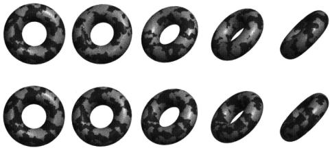
Figure 12.1 A torus with thresholded fBm indexed in "current" space will appear to be moving "through" the texture pattern as the object moves (top). If the fBm is calculated in . "shader" space, the pattern will stick to the surface as the object moves rigidly (bottom).
float f =float noise (P);
color Ct = mix (C1, C2, filterstep(.5, f)); Ci = Ct * (Ka*ambient() + Kd*diffuse(Nf)) +
specularcolor * Ks * specular(Nf,V);
P, the position of the point being shaded, is expressed in "current" space. What happens if the object is moving and you render several frames in a row? Figure 12.1 shows such a situation. The texture lookups are happening in "current" space (which is probably a "fixed" coordinate system such as "world" space or "camera" space). Because the object is moving relative to "current" space, it will appear to be traveling through the texture! This is almost certainly not the desired effect.
Although "current" space is necessary for lighting and certain other calculations, it is extremely inconvenient for texturing calculations. In addition, the exact nature of "current" space is renderer dependent and may vary among implementations. For these reasons, we never texture in "current" space.
12.2.2 Texture Spaces Rigidly Connected to the Geometry
If the object is moving rigidly--that is, its movement is due to changing its transformation-then the relationship between "world" space and "object" space changes from frame to frame. But the geometry is in a fixed position relative to its local or "object" space. The following shader fragment indexes the noise field using the "object" space coordinates of P:
point Pobj = transform ("object", P); float f =float noise (Pobj);
286 12 A Gallery of Procedural Shaders
color Ct = mix (Cl, C2, filterstep(.5, f));
.
.
.
As a further refinement, we observe that it may be convenient to rotate, translate, or scale the texture relative to the object geometry. Luckily, there is another coordinate system that can be structured to be rigidly connected to "object" space, yet can be independently transformed: "shader" space. Recall that "shader" space is the coordinate system that was active when the shader was declared. Below is a RIB fragment showing how "shader" space can be transformed relative to "object" space.
AttributeBegin |
# Translate, rotate, scale the object |
ConcatTransform [...] |
|
TransformBegin |
# Move shader relative to object |
ConcatTransform [...] |
|
Surface "noisy" |
# Specify the shader |
TransformEnd |
# Restore the object transformation |
PatchMesh ... |
# Make some geometry |
AttributeEnd |
|
In this example, we have inserted an additional transformation after the objectplacing transform but before the shader is declared (and then we restore the object transformation before declaring the geometry). This gives us an additional control over the placement and scaling of the texturing that is built into the model, provided we lookup our texture in "shader" space:
point Pshad = transform ("shader", P); float f =float noise (Pshad);
.
.
.
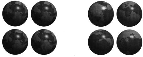
Another reason for preferring "shader" space over "object" space is that your model maybe comprised of different geometric primitives that have different object transformations. Yet you may prefer a single coordinate system for texturing that is independent of the individual object systems for each primitive. As a case in point, suppose your model contains (perhaps among other things) a number of spheres. Because spheres are always centered on their object coordinate spaces, shading in "object" space would result in each sphere having the same pattern on them. This is almost certainly not desired; rather, if texturing were performed in a single "shader" space, each sphere would be sampling a different part of the texture space. Furthermore, all of the primitives in the model would appear to be carved from the same block of texture. This is illustrated in Figure 12.2.
287
12.2 Aside: Shading Spaces and Reference Meshes
Figure 12.2 All spheres are centered at the origin of their local coordinate systems, so shading in "object" space will make spheres with identical patterns (left). Using "shader" space allows you to vary the pattern on identical primitives by making each one index texture from a different area of the pattern space (right).
12.2.3 Deformations and Reference Geometry
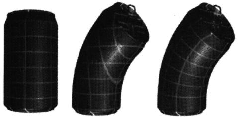
Using "shader" space for indexing 3D patterns prevents the texture from sliding along the surface but only as long as the object is undergoing rigid transformations-in other words, translation and rotation. But if your object is deforming, then its points are moving around within "shader" space. This is illustrated in Figure 12.3 (left and center), which shows a soda can with a solid grid texture applied in "shader" space. If the can is deformed by moving the control vertices of its mesh, then its points will move nonrigidly through "shader" space, and again we will be faced with the pattern sliding around on the geometry.
How can we attach texture to the deforming object in a way that will cause the pattern to stick to the surface? Recall that RenderMan allows you to attach arbitrary data to geometric meshes, with the renderer interpolating the data across the surface and providing it to the shader. What if the data being interpolated is the original, undeformed geometric positions of the mesh? We can use those coordinates as the basis for texturing, secure in the knowledge that they will "track" the surface regardless of what wacky deformations the surface undergoes. The solution to our sliding texture problem, then, is to construct the model with both the deformed position and an undeformed reference mesh used for texturing (see Section 4.7).
Because any shaders that create patterns based in some way on P will almost certainly want to transform to a shading space (generally, "shader" space), and often will want a reference mesh if the geometry may deform, let us create some reusable code that simplifies the process for us. There are two steps involved. First, the shader must include parameters for the name of the shading space and for Pref (if a reference mesh is provided). Second, we must transform either P or Pref
288 12 A Gallery of Procedural Shaders
Figure 12.3 Deforming the control mesh of an object will result in the texture sliding over the surface if the geometry moves nonrigidly (left and center). Using a reference mesh for texturing makes the texture "stick" to the deforming mesh (right). (Example and images courtesy of Shaun Oborn, Pixar Animation Studios.)
(depending on whether a reference mesh is provided) into the appropriate shading space. Listing 12.1 shows a header file that provides macros that perform these operations.
Listing 12.1, which lists pshad.h, defines three useful macros. PSHAD_PARAMS and DEFAULT_PSHAD_PARAMS both declare the necessary parameters shadingspace, which gives the name of the space in which to perform shading calculations, shadingfreq, which provides an additional means of scaling the frequency of the pattern, and Pref, the reference mesh position. You should write one of these macro names somewhere in the parameter list for your shader. While DEFAULT_PSHAD_PARAMS uses "shader" as the shading space and a frequency multiplier of 1, PSHAD_PARAMS takes two parameters that let you specify those defaults. Remember that in either case, the model may override these defaults by passing an explicit parameter to the shader declaration.
The GET_PSHAD macro sets the value of Pshad to the shading space coordinates of either P or Pref. Pref is used if it exists and appears to have data; otherwise, P is used. We pick an unlikely default value for Pref so that we can easily recognize if this value was overridden, indicating that the RIB stream contained Pref data for this geometric primitive. For good measure, the GET-PSHAD macro also declares and computes dPshad as an estimate of the amount that Pshad changes between adjacent shading samples. This can be used for antialiasing of your pattern-generation operations.
Finally, to eliminate the extra Pref storage and computation that is unnecessary for a rigid mesh, we use the preprocessor symbol USE_PREF. You should #define
289
12.2 Aside: Shading Spaces and Reference Meshes
Listing 12.1 pshad. h: a header file that provides the PSHAD_PARAMS and
GET_PSHAD macros.
/******************************************************************************
*pshad.h - define macros for easy use of reference meshes and texture
*spaces:
*PSHAD_PARAMS(space,freq) - put this macro in the parameter list of your
*shader to declare a shadingspace parameter (and
*optionally Pref, if USE-PREF is nonzero). Takes as
*arguments the default shading space name and frequency.
*DEFAULT_PSHAD_PARAMS - calls PSHAD-PARAMS with default space "shader"
*and default frequency 1.
*GET-PSHAD - put this in the body of your shader, near the top.
*It sets Pshad to the shading coordinates of P (or Pref,
*if provided), and sets dPshad to the expected change
*in Pshad between adjacent shading samples.
*This file expects that the .sl file #define's the symbol USE_PREF
*_prior_ to inclusion of this header file.
*/
/* If USE-PREF is not defined, assume that Pref will not be used. */ #ifndef USE-PREF
#define USE-PREF 0 #endif
#if (USE-PREF)
/* Pick an unlikely value to let us recognize an uninitialized Pref */ #define UNINITIALIZED_PREF point (-le10, -1e10, -1e10)
#define PSHAD_PARAMS(spacedefault,freqdefault) |
|
|
|
varying point Pref = UNINITIALIZED_PREF; |
\ |
|
string shadingspace = spacedefault; |
\ |
|
float shadingfreq = freqdefault; |
\ |
#define GET-PSHAD |
varying point Pshad; |
\ |
|
if (Pref != UNINITIALIZED_PREF) |
\ |
|
Pshad = transform (shadingspace, Pref); |
\ |
|
else Pshad = transform (shadingspace, P); |
\ |
|
Pshad *= shadingfreq; |
\ |
|
float dPshad = filterwidthp(Pshad); |
|
#else /* if (USE-PREF) */ |
|
|
#define PSHAD_PARAMS(spacedefault,freqdefault) |
\ |
|
|
string shadingspace = spacedefault; |
\ |
|
float shadingfreq = freqdefault; |
|

290 12 A Gallery of Procedural Shaders
Listing 12.1 (continued)
#define GET-PSHAD |
varying |
point Pshad; |
\ |
|
Pshad = |
shadingfreq * transform (shadingspace, P); |
\ |
float dPshad = filterwidthp(Pshad);
#endif /* USE-PREF */
#define DEFAULT_PSHAD_PARAMS PSHAD_PARAMS("shader",1)
this symbol prior to where you #include the pref.h file. If USE_PREF is nonzero, the PSHAD_PARAMS and GET_PSHAD macros will include the Pref declarations and operations. If USE_PREF is zero, these extra computations will be avoided in favor of somewhat simpler implementations of PSHAD_PARAMS and GET_PSHAD that do not consider Pref.
Following is an example of a shader that uses these macros:
#define USE-PREF 1 #include "filterwidth.h" #include "noises.h" #include "pshad.h"
surface
splotch (float Ka = 1, Kd = 0.5, Ks = .65, roughness = .1; color specularcolor = 1;
float octaves = 4, lacunarity = 2, gain = 0.5; DEFAULT_PSHAD_PARAMS )
{
GET_PSHAD;
float f = fBm (Pshad, dPshad, octaves, lacunarity, gain); color Ct = mix (color 1, color (.8, .1, 1), filterstep (0, f)); normal Nf = faceforward (normalize(N),I);
Ci = Ct * (Ka*ambient() + Kd*diffuse(Nf)) +
specularcolor * Ksf*specular(Nf,-normalize(I),roughness); Oi = Os; Ci *= Oi;
}
The overriding lesson of this section is: forget "current" space, it is quite undependable. It is better to always take steps to work in something dependable like "shader" space. Furthermore, if your object is undergoing nonaffine transformations or deformations, you will need to provide a reference mesh and use the interpolated reference positions for your pattern generation.
12.3 Ceramic Tiles |
291 |
|
12.3 Ceramic Tiles
For our first shader, we will create a procedural texture that resembles ceramic tiles, like the kind you often see lining the. walls and other surfaces of bathrooms or kitchens.
After long contemplation in the shower, this author made a list of the main features of the tiles:
■The tiles are square and arranged in a regular rectilinear pattern.
■The tiles themselves are ceramic, and slightly reflective, while the space between adjacent tiles is filled with dirty mortar.
■The tiles are slightly raised (or is the mortar pushed in?) and the corners of the tiles are rounded.
■The individual tiles tend to have a mottled appearance in the interior, shifting between different colors. There often seems to be another, usually darker, color around the outer border of each tile. Tiles also seem to have little dark specks occasionally.
■Each tile is different, with noticeable shifts in the overall color from tile to tile.
The basic structure of our shader will simply implement these features roughly in order. We will use comments to indicate where the features will be implemented. Notice that we are already considering both the visual appearance and the shader implementation to be organized in steps or layers.
surface
ceramictiles ( /* parameters */ )
{
/* Step 0: Get 2D texture coordinates for the texturing */
/* Step 1: Find out where in the pattern we are: whether we're in
*a tile section or a mortar section, which tile we're on,
*and the coordinates within our individual tile.
*/
/* Step 2, displacement: the edges of the tile displace down a bit,
*as do the grooves between tiles. Also, add just a little bit of
*per-tile normal variation to break up reflections.
*/
/ * Step 3: Set the color of the mortar between tiles and/or the color
*of our spot of tile (the tile texture itself, that is).
*/
/* Step 4: vary the color on a per-tile basis so that every tile
*looks a little different.
*/
12 A Gallery of Procedural Shaders
292
/* Step 5: Illumination model */ Ci = MaterialCeramicTiles (..
Oi = Os; Ci *= Oi;
}
For Step 0, we can make use of the ProjectTo2D routine that we presented in Section 8.3 to give the user great flexibility in defining texture projection spaces based on parameters to the shader. ProjectTo2D will set 2D texture coordinates ss and tt and their filter widths dss and dtt. All the routines that follow can probably be greatly simplified if we assume that tiles are one unit square (counting the mortar). So our preamble will "normalize" the texture coordinates in this manner.
Thus, we have
float ss, tt, dss, dtt;
ProjectTo2D (projection, P, textureprojspace, array_to_mx(mx), ss, tt, dss, dtt);
ss/= stilespacing; dss /= stilespacing;
tt/= ttilespacing; dtt /= ttilespacing;
where projection, textureprojspace, mx, stilespacing, and ttilespacing are all
parameters to our shader. Typical real-life tiles have a spacing of about 10 cm, with groove width of about 0.5 cm.
Now we turn to finding our place in the pattern. Recall the pulsetrain routine we discussed in Section 11.3.2. We can extend it to 2D by multiplying a pulse train in s with a pulse train in t,
pulsetrain (groovewidth, 1, ss+groovewidth/2) pulsetrain (grooveheight, 1, tt+grooveheight/2);
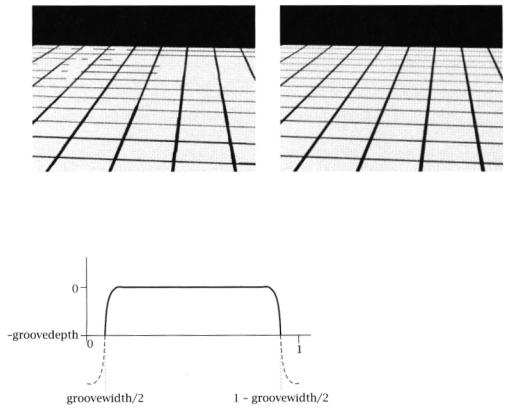
where groovewidth and grooveheight are the widths of the mortar grooves between tiles, expressed as a fraction of the tile-to-tile spacing (which we have assumed has been normalized to 1.0). This gives us the pattern in Figure 12.4 (left). Notice the bad aliasing-this results from the high frequencies of the infinitely sharp pulses. In some cases, the dark lines disappear altogether when they are so narrow that they fall "between" shading samples.
We can remedy this aliasing by using the filteredpulsetrain function instead (Figure 12.4, right). We must also compute which tile we are on (indexed by a 2D integer) and where in our particular tile we are shading:
swhichtile = floor (ss); twhichtile = floor (tt); stile = ss - swhichtile; ttile = tt - twhichtile;
intile = filteredpulsetrain (groovewidth, 1, ss+groovewidth/2, ds)
* filteredpulsetrain (grooveheight, 1, tt+grooveheight/2, dt);
293
12.3 Ceramic Tiles
Figure 12.4 Criss-crossing pulsetrains provide the basic structure of the tile pattern but alias badly (left). Using filteredpulsetrain serves to antialias the groove/tile pattern (right).
Figure 12.5 Profile of a tile displacement.
Next we want to make the tiles appear displaced. Rather than displacing the tiles up, we will displace the grooves down, which will avoid any strange intersection artifacts. Furthermore, we can probably get away with bump mapping, as the groove depth (typically only a couple millimeters) is probably very small in screen space. Figure 12.5 shows our desired tile profile. The mortar areas drop down to -groovedepth, the centers of the tile stay where they were, and we can use a smoothstep to round the corner of the tile. Note that we offset the smoothstep so that the tile corner is rounded, but we have a sharper transition where the tile meets the mortar. Here is the implementation of the displacement strategy:
float smoothpulse (float e0, el, e2, e3, x) {
return smoothstep(e0, e1, x) - smoothstep(e2, e3, 0;
}
float tiledisp = smoothpulse (0, .075, 0.925, 1, stile);