

нормальная рентгенанатомия легких
.pdf1
Normal Chest Radiograph
Nestor L. Müller and C. Isabela S. Silva
TECHNIQUE
Projections
The standard radiographic views for evaluation of the chest are the posteroanterior and lateral projections with the patient standing; such projections provide the essential requirement for proper three-dimensional assessment (Fig. 1-1). In patients who are too ill to stand, anteroposterior upright or supine projections offer alternative, but considerably less satisfactory views. The anteroposterior projection is of inferior quality because of the shorter focal-film distance, the greater magnification of the heart, and the restricted ability of many such patients to suspend respiration or achieve full inspiration.
Basic Radiographic Techniques
Diagnostic accuracy in chest disease is related partly to the quality of the radiographic images themselves. Careful attention to several variables is necessary to ensure such quality.
Patient Positioning
Positioning must be such that the x-ray beam is centered properly, the patient’s body is not rotated, and the scapulas are rotated sufficiently anteriorly that they are projected away from the lungs. The easiest method to determine whether the patient is properly positioned is to assess the distance between the medial ends of the clavicles (anterior structures) and the spinous processes of the thoracic vertebrae (posterior structures). In a properly centered radiograph, the medial ends of the right and left clavicles are equidistant from the spinous processes (Fig. 1-2). The American College of Radiology standards for performance of standard chest radiography in adults specify the use of at least a 72-inch (1.8 m) tube-film distance.1
Patient Respiration
Respiration must be suspended, preferably at full inspiration. On radiographs performed at low lung volumes, the mediastinum appears widened, the cardiopericardial silhouette appears enlarged, and the pulmonary vessels appear crowded and prominent.
Exposure
Exposure factors should be such that there is faint visualization of the thoracic spine and the intervertebral discs on the posteroanterior radiograph so that lung markings behind the heart are clearly visible. Exposure should be as short as possible, consistent with the production of adequate contrast. Exposure time should be less than 40 ms, and the maximum mean skin entrance radiation dose should be 0.3 mGy.1
Kilovoltage
A high-kilovoltage technique (115 to 150 kVp) should be used for posteroanterior and lateral chest radiographs.1 The abbreviation kVp is the peak voltage applied across the x-ray tube. The high kVp allows better penetration of the mediastinum and shorter exposure times, thus minimizing cardiac motion artifacts and providing sharper outline of the pulmonary and mediastinal structures. Because high kVp results in increased scatter radiation, grids (10 : 1 or 12 : 1) are required to reduce image degradation. Use of a grid increases contrast by removal of scatter and improves the signal-to-noise ratio, particularly in the mediastinum.1
Conventional Film-Screen Radiography
Conventional chest radiography uses film to capture, display, and store the images. Film has several advantages, including easy handling, high sensitivity, and good
3
4 P A R T O N E ● Normal Chest
A B
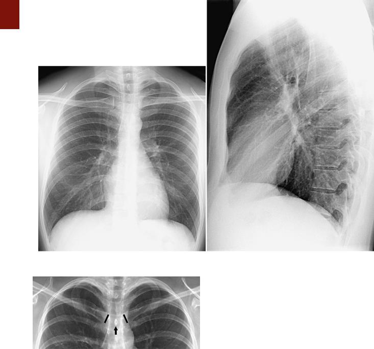
■ FIGURE 1-1 Normal chest radiograph. A, Posteroanterior projection. B, Lateral projection.
■ FIGURE 1-2 Properly centered chest radiograph. A view from a frontal radiograph shows that the medial ends of the right and left clavicles (highlighted in black) are equidistant to the spinous process (arrow) of the vertebra at the same level, thus indicating that the radiograph is properly centered.
uniformity; however, it is limited by the small exposure range over which it provides diagnostic information. The thorax ranges from the nearly radiotransparent lung to the highly attenuating mediastinum, rib cage, and spine. Adequate visualization of these various structures on conventional film requires wide-latitude film. Other techniques that have been used include customized patient-specific filters2 and scanning equalization radiography.3 The latter
technique incorporates a feedback system that modulates the intensity of the x-ray beam according to the patient’s body habitus. Despite these developments, conventional film-screen radiography has a number of limitations and therefore has been replaced by computed radiography (CR) and digital radiography in many centers.
Computed Radiography and
Digital Radiography
The process of acquisition, transmission, display, and storage of digital images has many advantages over conventional screen-film systems.4,5 One of the most important is its wide exposure latitude, which is 10 to 100 times greater than the widest dynamic range of screen-film systems. During digital image processing, the systems automatically determine the range of clinically appropriate gray levels and produce an image within that range.
As a result, the final image is virtually independent of absolute x-ray exposure levels. A potential disadvantage is that patients may receive unnecessarily high radiation doses, which may not be detected because they do not result in perceivable alterations in image quality.
The wider latitude of digital systems allows them to be used under a much broader range of exposure conditions

than possible with conventional systems and makes them an ideal choice for applications in which exposure is highly variable or difficult to control, such as bedside radiography. Another major advantage of digital radiography is that it produces what are essentially electronic images; as a result, an image may be transmitted to any location, displayed at multiple sites simultaneously, and efficiently archived for later reference. The images can be distributed widely by using picture archiving and communications systems (PACS), displayed on video monitors (soft copy), or printed onto film or paper (hard copy). Two main types of digital systems are available commercially: systems based on photostimulable storage phosphor image receptors, known as CR, and systems based on flat-panel x-ray detectors or array of detectors that directly capture the radiographic image, known as digital radiography.
CR (storage phosphor radiography) involves the use of a reusable photostimulable phosphor plate rather than film to record the image. Plates coated with the phosphor are loaded into special cassettes that are outwardly similar to screen-film cassettes. During exposure, the receptor stores the x-ray energy and is then scanned by a laser beam, which results in the creation of visible or infrared radiation, the intensity of which corresponds to the absorbed x-ray energy. The resultant luminescence is measured and recorded digitally.6 CR has been used mainly for bedside chest radiography because its wide dynamic range allows it to achieve consistent images over a wide range of x-ray exposure.7 Storage phosphor systems have a dynamic range of approximately 1 : 10,000, as opposed to 1 : 100 for standard films8; that is, they are capable of producing diagnostic images over a much broader range of exposure, which results in a considerable decrease in the repeat rate for bedside chest radiographs.9
Other advantages of CR over the conventional filmbased system are its greater contrast resolution and suitability for computer image processing. Images have a more reproducible quality, thereby resulting in a reduction in the retake rate. However, photostimulable phosphors have lower spatial resolution than conventional film systems do and greater sensitivity to the lower energy components of the x-ray spectrum and are therefore more susceptible to degradation by scatter.10 Consequently, it is important to use an antiscatter grid for adult portable chest radiography to adequately visualize the parenchyma and the mediastinum and to assess the location of catheters and other devices in the mediastinum.10
A major limitation of CR is the need for separately reading the phosphor plate after exposure, which is time consuming not only because of the process itself but also because of the necessity to bring the cassette to CR plate readers. Despite these limitations, CR is currently the most practical option for portable radiography.10 In most other areas of radiography, however, CR is rapidly being replaced by digital radiography.10
Digital Radiography
Digital radiography uses a flat-panel x-ray detector or array of detectors to directly capture the radiographic image numerically, thus eliminating the step of reading
C H A P T E R 1 ● Normal Chest Radiograph |
5 |
out the detector. The detectors in digital radiography are selenium based and provide the additional advantage of having considerably greater quantum efficiency than conventional screen-film systems and photostimulable phosphor detectors do.11,12 This high detection efficiency allows image quality superior to that of screen-film systems and existing storage phosphor detectors at a comparable or lower radiation dose.10 The main disadvantage of digital radiography at the current time is its relatively high cost.
NORMAL ANATOMY OF THE CHEST
Airways
Trachea and Bronchi
The trachea is a midline structure, and the tracheal walls are parallel except on the left side just above the bifurcation, where the aorta commonly causes a smooth indentation (Fig. 1-3). In older individuals, unfolding and ectasia of the aorta lead to deviation of the lower part of the trachea to the right. The trachea measures 10 to 12 cm in length and has 16 to 20 U-shaped cartilage rings on its lateral and anterior aspects and a fibromuscular posterior margin. Calcification of the cartilage rings is a common normal finding in patients older than 40 years, particularly women, but it is seldom evident on radiographs (Fig. 1-4). The upper limits of normal for coronal and sagittal diameters of the trachea in men are 25 and 27 mm, respectively; in women, they are 21 and 23 mm.13 The lower limit of normal for both dimensions is 13 mm in men and 10 mm in women.13
The trachea divides into the left and right main bronchi at the carina, at approximately the level of the fifth thoracic vertebra. The subcarinal angle ranges from 35 to 90 degrees (mean, 61 degrees).14 Because of the wide range, measurement of the subcarinal angle is seldom helpful in the detection of abnormalities.
The right main bronchus measures approximately 2 cm in length and has a more vertical course than the left main bronchus does (see Fig. 1-3). It divides into the right upper lobe bronchus and the bronchus intermedius.
The bronchus intermedius continues distally for 3 to 4 cm from the takeoff of the right upper lobe bronchus and then bifurcates into bronchi to the middle and lower lobes. The left main bronchus is approximately 5 cm in length and divides into the left upper and lower lobe bronchi.
The lobar bronchi branch into segmental bronchi. Segmental bronchi are visible on chest radiographs only when they are seen end-on as ring shadows or when they are abnormally thickened. The most commonly seen segmental bronchi on a chest radiograph are the anterior segmental bronchi of the upper lobes. These bronchi are seen as ring shadows adjacent to the accompanying segmental pulmonary artery (Fig. 1-5). On an upright chest radiograph the diameter of the anterior segmental bronchus of the upper lobe (approximately 5 mm) is slightly larger than that of the adjacent segmental pulmonary artery. The anatomy of the segmental bronchi and smaller airways is illustrated in Chapter 2.
6 P A R T O N E ● Normal Chest
A B
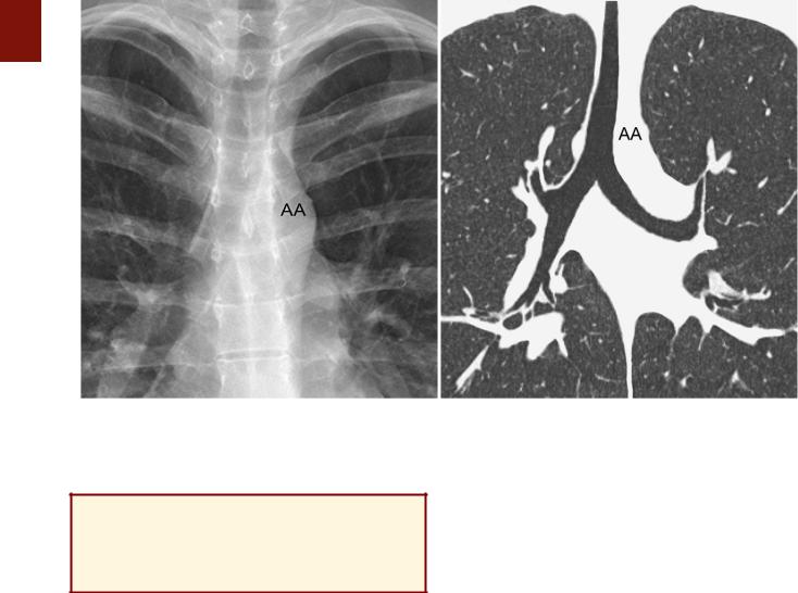
■ FIGURE 1-3 Normal trachea and main bronchi. A, View from a frontal radiograph showing that the tracheal air column is fairly straight and located in the midline except at the level of the aortic arch (AA), where the trachea is indented and may be slightly deviated to the right. The trachea divides into a short right main bronchus and a longer and more horizontal left main bronchus. B, Coronal reformatted image from a CT scan demonstrating the normal anatomy of the trachea, the slight indentation at the level of the aortic arch (AA), and the main bronchi. Approximately
2 cm after its origin the right main bronchus branches into the right upper lobe bronchus and the bronchus intermedius.
KEY POINTS: TRACHEA
■Normal diameter in men: 13 to 27 mm
■Normal diameter in women: 10 to 23 mm
■Normal subcarinal angle: 35 to 90 degrees
Pulmonary Arterial and
Venous Circulation
Pulmonary Arteries
The main pulmonary artery originates in the mediastinum at the pulmonary valve and extends cranially and slightly to the left for 4 to 5 cm before bifurcating within the pericardium into the shorter left and longer right arteries (Fig. 1-6). The left pulmonary artery continues in more or less the same line as the pulmonary trunk until it reaches the hilum, where it arches over the left main bronchus. Subsequently, the artery sometimes gives off a short ascending branch that divides into segmental branches to the upper lobe; more commonly, it continues directly into the vertically oriented left interlobar artery, from which segmental arteries to the upper and lower lobes arise directly. The left interlobar artery lies posterolateral to the upper lobe bronchus.
The right pulmonary artery courses behind the ascending aorta before dividing behind the superior vena cava (SVC) and in front of the right main bronchus into ascending (truncus anterior) and descending (interlobar) branches
(Fig. 1-6). Though variable, the common pattern is for the ascending artery to subdivide into segmental branches that supply the right upper lobe and for the descending branch to contribute segmental arteries to the middle and right lower lobes.
The first portion of the right interlobar artery is horizontal and interposed between the SVC in front and the intermediate bronchus behind (Fig. 1-6). It then turns sharply downward and backward and assumes a vertical orientation within the major fissure (thus its name) anterolateral to the intermediate and right lower lobe bronchi before giving off segmental branches, one or two to the middle lobe and usually single branches to each of the five bronchopulmonary segments of the lower lobe.
Although the course of the most proximal pulmonary arteries is fairly constant, the origin and branching pattern of the lobar and segmental arteries show considerable variation. Despite this variation, the pulmonary arterial system is invariably intimately related to the airways and divides with them, and a branch always accompanying the adjacent airway down to the level of the distal respiratory bronchioles.
Measurements of pulmonary arterial diameter can be helpful in the assessment of pulmonary vascular disease. Because the more proximal vessels are not well seen on radiographs, measurement of large pulmonary arteries is usually limited to the right interlobar artery. The upper limit of normal of the transverse diameter of the interlobar artery (measured from its lateral aspect to the air column of the intermediate bronchus) is 16 mm in men and 15 mm in women (Fig. 1-7).15 Dilation of the interlobar pulmonary
C H A P T E R 1 ● Normal Chest Radiograph |
7 |
|
|
|
|
|
|
|
A B
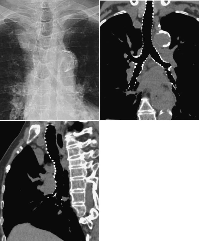
■ FIGURE 1-4 Tracheal and bronchial wall calcification. A magnified view from a posteroanterior chest radiograph (A) in an elderly patient shows calcification of the tracheal and bronchial walls. Coronal (B) and sagittal (C) reformatted images from a multidetector CT scan show the extent of tracheal and bronchial calcification. Airway wall calcification is a
C normal finding in elderly patients. The patient was an 84-year-old woman.
8 P A R T O N E ● Normal Chest
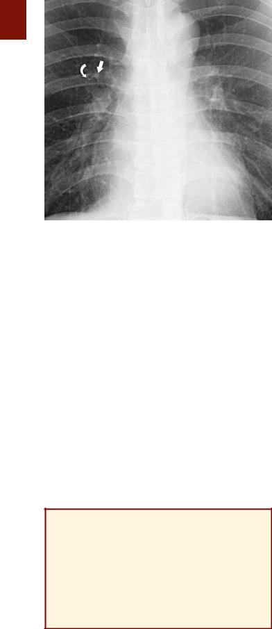
■ FIGURE 1-5 Anterior segmental bronchus of the right upper lobe seen end-on. A view from a frontal radiograph shows a ring shadow (curved arrow) corresponding to the anterior segmental bronchus of the right upper lobe seen end-on and the adjacent anterior segmental
pulmonary artery (straight arrow). The outer diameter of the bronchus on the upright chest radiograph is slightly larger than that of the adjacent artery.
artery may result from increased pressure (e.g., pulmonary arterial hypertension), increased flow (e.g., left-to-right shunts), or aneurysm formation (e.g., Behçet’s disease) (Fig. 1-8).
Another measurement that can be useful is the pulmonary artery–to-bronchus diameter ratio. In a study of 30 healthy individuals, the ratio on frontal radiographs was
0.85± 0.15 (mean ± standard deviation) above and 1.34 ±
0.25below the right hilar angle in the erect position (see Fig. 1-5) and 1.01 ± 0.13 above and 1.05 ± 0.13 below the right hilar angle in the supine position.16 Calculation of these ratios is particularly helpful in the assessment of volume overload and congestive heart failure. For example, in a study of 30 patients with volume overload complicat-
ing chronic renal failure, the mean artery-to-bronchus ratio in the erect position was 1.62 ± 0.31 above the right hilar angle and 1.56 ± 0.28 below it; in patients who had congestive heart failure, the ratio was 1.50 ± 0.25 above and 0.87
± 0.20 below in the erect position and 1.49 ± 0.31 above and 0.96 ± 0.31 below in the supine position.16
KEY POINTS: PULMONARY
ARTERIES
■Normal diameter of the right interlobar pulmonary artery: <16 mm
■Normal pulmonary artery–to-bronchus diameter ratio:
●Upright chest radiograph: above the right hilum, 0.85
±0.15
●Upright chest radiograph: below the right hilum, 1.34
±0.25
●Supine chest radiograph: 1.04 ± 0.13
Pulmonary Veins
The pulmonary veins arise from venules that drain the alveolar capillaries and the capillary network of the pleura. In contrast to the pulmonary arteries, they are not associated with the airways. Although their final course is variable, there are usually two main superior and two main inferior vessels, the former draining the middle and upper lobes on the right side and the upper lobe on the left and the latter draining the lower lobes (Fig. 1-9). The rightsided veins course beneath the main pulmonary artery posterior to the SVC and enter the left atrium separately. The left-sided veins pass anterior to the descending aorta and enter the atrium separately as on the right or join within the pericardial cavity to enter the atrium as a common channel. As in the pulmonary arterial system, numerous supernumerary vessels join the veins as they course through the lung.
Pulmonary Hila
The pulmonary hila are areas in the center of the thorax that connect the mediastinum to the lungs. The anatomic structures rendering the hila visible on radiographs are primarily the pulmonary arteries and veins, with lesser contributions from the bronchial walls, surrounding connective tissue, and lymph nodes (Fig. 1-10).
On a posteroanterior radiograph the main shadow of the right hilum is formed by the vertically oriented interlobar artery. Right hilar structures immediately cephalad to the interlobar artery include the ascending pulmonary artery and superior pulmonary vein (Fig. 1-11). The end-on opacity and radiolucency of the contiguous anterior (and occasionally posterior) segmental artery and bronchus can be identified in approximately 80% of normal individuals.17 On an upright chest radiograph the anterior segmental bronchus normally measures approximately 5 mm in diameter and has a wall thickness of 1 mm or less and a diameter slightly greater than that of the adjacent artery (see Fig. 1-5).
The right superior pulmonary vein can often be seen as it crosses the junction of the horizontal and vertical limbs of the interlobar artery and the respective branches of these vessels. The horizontally oriented inferior pulmonary vein lies more inferiorly. The radiolucent lumen of the intermediate bronchus can be invariably identified medial to the interlobar artery. Occasionally, segmental bronchi and arteries in the middle and lower lobes can be seen in profile or end-on.
On the left, the upper hilar opacity is formed by the distal left pulmonary artery, the proximal portion of the left interlobar artery and its segmental arterial branches, and the left superior pulmonary vein and its major tributaries. Because the left pulmonary artery arches over the left main and left upper lobe bronchi, the left hilum is typically 1 to 2 cm higher than the highest point of the right hilum (right interlobar artery) (see Fig. 1-10).
Surrounding the hilar vessels and bronchi are small amounts of fat and small lymph nodes. They cannot normally be distinguished from other structures on the radiograph. Enlargement of the hilar lymph nodes leads to
C H A P T E R 1 ● Normal Chest Radiograph |
9 |
|
|
|
|
|
|
|
A B
C
increased size and opacity of the hilum, a lobulated contour, and obscuration of the interlobar artery (Fig. 1-12). Masses situated in front of or behind the hilum result in increased opacity of the hilar shadow but do not obscure the margins of the interlobar artery. This finding is known as the hilum overlay sign.
The radiographic anatomy of the hila on a lateral projection is complex because the right and left hilar components are to a large degree superimposed (Fig. 1-13).18,19 The trachea is usually well seen down to the level of the carina. The level of the carina can be identified because it is the level where the air column can be seen to taper (Fig. 1-13). At the level of the carina the left pulmonary artery can be seen as a curved structure as it courses above the left main bronchus and continues as the descending
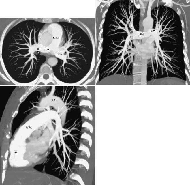
■ FIGURE 1-6 Normal anatomy of the central pulmonary arteries. A, A maximum intensity projection image obtained from a CT scan
demonstrates that the main pulmonary artery (MPA) courses posteriorly and branches into the right (RPA) and left (LPA) pulmonary arteries. The right pulmonary artery branches shortly after its origin into the truncus anterior, which courses cephalad to supply most of the right upper lobe, and a larger right interlobar pulmonary artery (RI), which courses just anterior and then lateral to the bronchus intermedius (BI). B, Coronal image from a CT scan demonstrating the orientation of the right (RPA) and left pulmonary arteries (LPA) in the same projection as the frontal radiograph. The right pulmonary artery and the central portion of the left pulmonary artery are in the mediastinum and therefore cannot be identified on the chest radiograph. The right pulmonary artery branches into the truncus anterior (TA) and right interlobar pulmonary artery (RI). C, Sagittal image demonstrating the orientation of the right and left pulmonary arteries that corresponds to the lateral chest radiograph. The main pulmonary artery (MPA) originates from the right ventricle (RV) and courses cephalad and posteriorly. AA, aortic arch; asterisk, aortopulmonary window.
left pulmonary artery. The air column of the normally more cephalic right upper lobe bronchus can be identified end-on as a rounded radiolucency in 50% of subjects, whereas that of the more caudal left upper lobe bronchus is seen in about 75%.19 The orifice of the right upper lobe bronchus is seldom as well circumscribed as that of the left because the latter is completely surrounded by vessels (the left pulmonary artery above, the descending artery behind, and the mediastinal component of the left superior pulmonary vein in front) whereas the former is devoid of vascular envelopment on its posterior aspect such that aerated upper or lower lobe parenchyma normally abuts its wall. Consequently, clear identification of the right upper lobe bronchial lumen en face constitutes highly suggestive evidence that the airway is completely
10 P A R T O N E ● Normal Chest
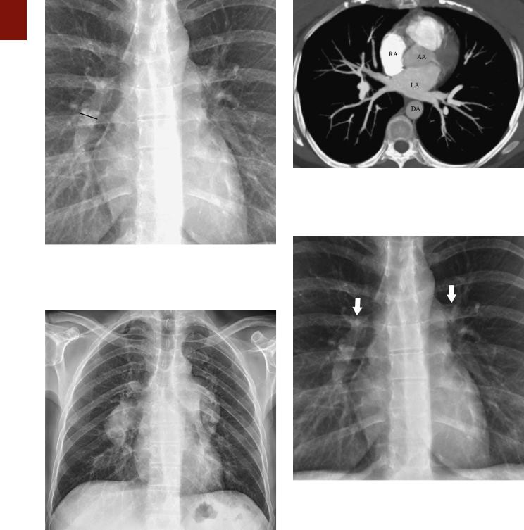
■ FIGURE 1-7 Normal right interlobar artery visualized on a frontal chest radiograph. The upper limit of normal of the transverse diameter of the interlobar artery measured from its lateral aspect to the air column of the intermediate bronchus is 16 mm in men and 15 mm in women.
■ FIGURE 1-8 Enlarged central pulmonary arteries. A frontal radiograph in a patient with severe pulmonary arterial hypertension shows markedly enlarged central pulmonary arteries.
surrounded by soft tissue, most likely enlarged lymph nodes.
Below the level of the carina, a line continuous with the posterior tracheal wall represents the posterior wall of the right main and intermediate bronchi and is known as the intermediate stem line (Fig. 1-13). The posterior
■ FIGURE 1-9 Inferior pulmonary veins. A maximum intensity projection image obtained from a CT scan shows two main right and left inferior pulmonary veins as they drain into the left atrium (LA). AA, ascending aorta; DA, descending aorta; RA, right atrium.
■ FIGURE 1-10 Normal hila. A view from a frontal radiograph shows that the main shadow of the right hilum is formed by the vertically oriented interlobar artery (arrow) and that of the left hilum by the distal left pulmonary artery (arrow) and descending left pulmonary artery. Because the left pulmonary artery arches above the left main and left upper lobe bronchi, the left hilum is normally 1 to 2 cm higher than
the right hilum.
wall of the right upper lobe and bronchus intermedius is rendered visible by air in their lumina in front and by aerated lung parenchyma in the azygoesophageal recess behind. On a well-centered lateral projection, the intermediate stem line transects the middle or posterior third of the circular, radiolucent left upper lobe bronchus; it terminates caudally at the origin of the superior segmental
■ FIGURE 1-12 Enlarged bilateral hilar lymph nodes. A frontal chest radiograph in a patient with sarcoidosis shows a lobulated contour of the hila and increased size and opacity, findings characteristic of hilar lymph node enlargement.
bronchus of the right lower lobe, slightly proximal to or at the same level as the origin of the middle lobe bronchus anteriorly. The intermediate stem line is visible in 95% of individuals and normally measures 1 to 3 mm in thickness.19,20 The intermediate stem line can become abnor-
C H A P T E R 1 ● Normal Chest Radiograph |
11 |
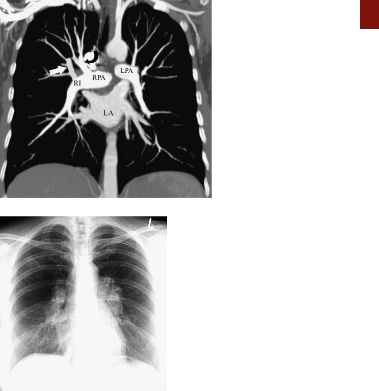
■ FIGURE 1-11 Normal hilar anatomy. A coronal image from a CT scan demonstrates the hilar anatomy as seen on a radiograph. The main right pulmonary artery (RPA) is in the mediastinum and therefore not visible on the frontal radiograph. On a frontal radiograph the main shadow of the right hilum is formed by the vertically oriented interlobar artery (RI). Right hilar structures immediately cephalad to the interlobar artery include the ascending pulmonary artery (truncus anterior) (curved arrow) and the right superior pulmonary vein (straight arrow). Most of the left hilum is formed by the distal left pulmonary artery (LPA) and left descending pulmonary artery.
mally thickened in the presence of right hilar disease, most commonly right hilar lymphadenopathy.21
On a lateral view, the right hilar opacity is composed of the superior pulmonary vein anteriorly, the ascending and descending right pulmonary arteries posteriorly, and surrounding connective tissue and lymph nodes. The right pulmonary artery is a mediastinal vessel enveloped by other vessels or soft tissue elements and is therefore not seen on the radiograph. The major portion of the left hilar vasculature is visible behind the intermediate stem line. The top of the left pulmonary artery is seen in 95% of subjects, usually as a sharply marginated opacity above and behind the radiolucency of the left upper lobe bronchus. Immediately posterior to this bronchus is the continuation of the left pulmonary artery, the descending left artery (Fig. 1-14; see also Fig. 1-13). The left superior pulmonary vein, like its counterpart on the right, is closely associated with the arterial vasculature of the hilum; however, this vein is not a contour-forming vessel on lateral radiographs and thus cannot be identified.
The right and left inferior pulmonary veins are commonly imaged end-on as a result of their horizontal orientation, with a nodular opacity created below and behind the lower portion of the hila. Fortunately, vessels can generally be identified as they converge toward the opacity, thereby permitting their distinction from a true parenchymal mass.
The shadows of the right hilum in front of the main bronchi and left pulmonary artery as it courses over the left main and upper lobe bronchi result in an inverted U appearance known as the “inferior hilar window” (Fig. 1- 13). Normally, there are no large vessels coursing immediately below the middle and lower lobe bronchi on the
12 P A R T O N E ● Normal Chest
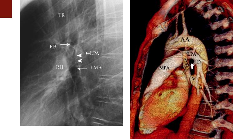
■ FIGURE 1-13 Normal hilar anatomy on a lateral chest radiograph. A magnified view of the hila from a lateral radiograph shows the trachea (TR) tapering off at the level of the carina immediately above the level of the left pulmonary artery (LPA), which is seen as a curved structure as it courses above the left main bronchus (LMB) and continues as the descending left pulmonary artery. The air column of the right upper lobe bronchus (RB) is seen at the level of the carina. The posterior wall of the trachea is continuous with the posterior wall of the right main and intermediate bronchi, which form a line know as the intermediate stem line (arrowheads). The right hilum (RH) is located anterior to the right intermediate bronchus (bronchus intermedius).
■ FIGURE 1-14 Normal left hilar anatomy on a lateral projection. A volume-rendering image from a CT scan shows the main pulmonary artery (MPA) and the left pulmonary artery (LPA), which arches over the left main and upper lobe bronchi (arrow) and continues as the left descending pulmonary artery (D). The arch of the LPA is parallel to that of the aortic arch (AA), and the space between them is the region of the aortopulmonary window. Also noted are pulmonary veins (V) draining into the left atrium.
right and the upper and lower lobe bronchi on the left. Therefore, any rounded opacity greater than 1 cm in the inferior hilar window on a lateral view is likely to be an enlarged node or a mass (Fig. 1-15).
Bronchial Circulation
There is considerable variation in the number and origin of human bronchial arteries. Most individuals have two to four, with a relatively common pattern being one on the right (originating from the third intercostal artery, which is the first right intercostal artery that arises directly from the aorta) and two on the left (arising directly from the descending aorta).22 The right and left bronchial arteries arise at the level of or slightly lower than the tracheal carina.23 Their normal diameter at the hilum is about 1 to 1.5 mm. The intrapulmonary bronchial arteries are situated within the peribronchial connective tissue and branch with the airways. They continue as far as the terminal bronchioles.
The bronchial circulation is unique in that it has dual venous drainage. One portion, related predominantly to
the trachea and large bronchi, drains through the bronchial veins to the right side of the heart via the azygos and hemiazygos systems. A second portion, related to the major portion of the intrapulmonary bronchial flow, is derived from extensive anastomoses with the pulmonary circulation at precapillary, capillary, and postcapillary sites and drains into the left atrium via the pulmonary veins (bronchopulmonary anastomotic flow).
Lung Parenchyma
Secondary Lobule
The secondary lobule is the smallest discrete portion of the lung that is surrounded by connective tissue septa.24
Each lobule is supplied by a lobular bronchiole and pulmonary artery, which are located in the center of the lobule; the draining pulmonary veins are located in the interlobular septa. The lobule is irregularly polyhedral in shape and generally measures 1 to 2.5 cm in diameter.22 Interlobular septa are most numerous in the apical, anterior, and lateral aspects of the upper lobe and the lateral