

HID1_11
.pdfRequests 51
Remarks
Description
Parts
Remarks
The following table defines valid values of bRequest.
Value |
Description |
0x01 |
GET_REPORT 1 |
0x02 |
GET_IDLE |
0x03 |
GET_PROTOCOL 2 |
0x04-0x08 |
Reserved |
0x09 |
SET_REPORT |
0x0A |
SET_IDLE |
0x0B |
SET_PROTOCOL 2 |
1This request is mandatory and must be supported by all devices.
2This request is required only for boot devices.
7.2.1 Get_Report Request
The Get_Report request allows the host to receive a report via the Control pipe.
Part |
Description |
bmRequestType |
10100001 |
bRequest |
GET_REPORT |
wValue |
Report Type and Report ID |
wIndex |
Interface |
wLength |
Report Length |
Data |
Report |
zThe wValue field specifies the Report Type in the high byte and the Report ID in the low byte. Set Report ID to 0 (zero) if Report IDs are not used. Report Type is specified as follows:
Value |
Report Type |
01 |
Input |
02 |
Output |
03 |
Feature |
04-FF |
Reserved |
zThis request is useful at initialization time for absolute items and for determining the state of feature items. This request is not intended to be used for polling the device state on a regular basis.
zThe Interrupt In pipe should be used for recurring Input reports. The Input report reply has the same format as the reports from Interrupt pipe.
zAn Interrupt Out pipe may optionally be used for low latency Output reports. Output reports over the Interrupt Out pipe have a format that is identical to output reports that are sent over the Control pipe, if an Interrupt Out endpoint is not declared.
6/277/00:

52 Device Class Definition for Human Interface Devices (HID) Version 1.11
Description
Parts
Remarks
7.2.2 Set_Report Request
The Set_Report request allows the host to send a report to the device, possibly setting the state of input, output, or feature controls.
Part |
Description |
|
|
bmRequestType |
00100001 |
bRequest |
SET_REPORT |
wValue |
Report Type and Report ID |
wIndex |
Interface |
wLength |
Report Length |
Data |
Report |
zThe meaning of the request fields for the Set_Report request is the same as for the Get_Report request, however the data direction is reversed and the Report Data is sent from host to device.
zA device might choose to ignore input Set_Report requests as meaningless. Alternatively these reports could be used to reset the origin of a control (that is, current position should report zero). The effect of sent reports will also depend on whether the recipient controls are absolute or relative.
7.2.3 Get_Idle Request
Description |
The Get_Idle request reads the current idle rate for a particular Input report (see: |
|
|
Set_Idle request). |
|
Parts |
Part |
Description |
|
|
|
|
bmRequestType |
10100001 |
|
bRequest |
GET_IDLE |
|
wValue |
0 (zero) and Report ID |
|
wIndex |
Interface |
|
wLength |
1 (one) |
|
Data |
Idle rate |
Remarks |
For the meaning of the request fields, refer to Section 7.2.4: Set_Idle Request. |
|
7.2.4 Set_Idle Request
Description |
The Set_Idle request silences a particular report on the Interrupt In pipe until a |
|
|
new event occurs or the specified amount of time passes. |
|
Parts |
Part |
Description |
|
bmRequestType |
00100001 |
|
bRequest |
SET_IDLE |
|
wValue |
Duration and Report ID |
|
wIndex |
Interface |
|
wLength |
0 (zero) |
|
Data |
Not applicable |
6/27/00:
|
|
Requests |
53 |
Remarks |
This request is used to limit the reporting frequency of an interrupt in endpoint. |
|
|
|
Specifically, this request causes the endpoint to NAK any polls on an interrupt in |
||
|
endpoint while its current report remains unchanged. In the absence of a change, |
||
|
polling will continue to be NAKed for a given time-based duration. This request |
||
|
has the following parts. |
|
|
|
Part |
Description |
|
|
|
|
|
|
Duration |
When the upper byte of wValue is 0 (zero), the duration is indefinite. |
|
|
|
The endpoint will inhibit reporting forever, only reporting when a |
|
|
|
change is detected in the report data. |
|
|
|
When the upper byte of wValue is non-zero, then a fixed duration is |
|
|
|
used. The duration will be linearly related to the value of the upper byte, |
|
|
|
with the LSB being weighted as 4 milliseconds. This provides a range of |
|
|
|
values from 0.004 to 1.020 seconds, with a 4 millisecond resolution. If |
|
|
|
the duration is less than the device polling rate, then reports are |
|
|
|
generated at the polling rate. |
|
|
|
If the given time duration elapses with no change in report data, then a |
|
|
|
single report will be generated by the endpoint and report inhibition will |
|
|
|
begin anew using the previous duration. |
|
|
Report ID |
If the lower byte of wValue is zero, then the idle rate applies to all input |
|
|
|
reports generated by the device. When the lower byte of wValue is non- |
|
|
|
zero, then the idle rate only applies to the Report ID specified by the |
|
|
|
value of the lower byte. |
|
|
Accuracy |
This time duration shall have an accuracy of +/-(10% + 2 milliseconds) |
|
|
Latency |
A new request will be executed as if it were issued immediately after the |
|
|
|
last report, if the new request is received at least 4 milliseconds before |
|
|
|
the end of the currently executing period. If the new request is received |
|
|
|
within 4 milliseconds of the end of the current period, then the new |
|
|
|
request will have no effect until after the report. |
|
If the current period has gone past the newly proscribed time duration, then a report will be generated immediately.
If the interrupt in endpoint is servicing multiple reports, then the Set_Idle request may be used to affect only the rate at which duplicate reports are generated for the specified Report ID. For example, a device with two input reports could specify an idle rate of 20 milliseconds for report ID 1 and 500 milliseconds for report ID 2.
The recommended default idle rate (rate when the device is initialized) is 500 milliseconds for keyboards (delay before first repeat rate) and infinity for joysticks and mice.
6/277/00:

54 Device Class Definition for Human Interface Devices (HID) Version 1.11
7.2.5 Get_Protocol Request
Description |
The Get_Protocol request reads which protocol is currently active (either the boot |
||
|
protocol or the report protocol.) |
|
|
Parts |
Part |
Description |
|
|
|
|
|
|
bmRequestType |
10100001 |
|
|
bRequest |
GET_PROTOCOL |
|
|
wValue |
0 |
(zero) |
|
wIndex |
Interface |
|
|
wLength |
1 |
(one) |
|
Data |
0 |
= Boot Protocol |
|
|
1 |
= Report Protocol |
Remarks |
This request is supported by devices in the Boot subclass. The wValue field |
||
|
dictates which protocol should be used. |
|
|
7.2.6 Set_Protocol Request
Description |
The Set_Protocol switches between the boot protocol and the report protocol (or |
||
|
vice versa). |
|
|
Parts |
Part |
Description |
|
|
bmRequestType |
00100001 |
|
|
bRequest |
SET_PROTOCOL |
|
|
wValue |
0 |
= Boot Protocol |
|
|
1 |
= Report Protocol |
|
wIndex |
Interface |
|
|
wLength |
0 |
(zero) |
|
Data |
Not Applicable |
|
Remarks |
This request is supported by devices in the boot subclass. The wValue field |
||
|
dictates which protocol should be used. |
|
|
When initialized, all devices default to report protocol. However the host should not make any assumptions about the device’s state and should set the desired protocol whenever initializing a device.
6/27/00:
Report Protocol |
55 |
8. Report Protocol
8.1 Report Types
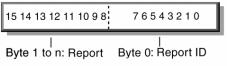
Reports contain data from one or more items. Data transfers are sent from the device to the host through the Interrupt In pipe in the form of reports. Reports may also be requested (polled) and sent through the Control pipe or sent through an optional Interrupt Out pipe. A report contains the state of all the items (Input, Output or Feature) belonging to a particular Report ID. The software application is responsible for extracting the individual items from the report based on the Report descriptor.
All of the items’ values are packed on bit boundaries in the report (no byte or nibble alignment). However, items reporting Null or constant values may be used to byte-align values, or the Report Size may be made larger than needed for some fields simply to extend them to a byte boundary.
The bit length of an item’s data is obtained through the Report descriptor (Report Size * Report Count). Item data is ordered just as items are ordered in the Report descriptor. If a Report ID tag was used in the Report descriptor, all reports include a single byte ID prefix. If the Report ID tag was not used, all values are returned in a single report and a prefix ID is not included in that report.
8.2 Report Format for Standard Items
The report format is composed of an 8-bit report identifier followed by the data belonging to this report.
Report ID
The Report ID field is 8 bits in length. If no Report ID tags are used in the Report descriptor, there is only one report and the Report ID field is omitted.
Report Data
The data fields are variable-length fields that report the state of an item.
6/277/00:

56 Device Class Definition for Human Interface Devices (HID) Version 1.11
8.3 Report Format for Array Items
Each button in an array reports an assigned number called an array index. This can be translated into a keycode by looking up the array elements Usage Page and Usage. When any button transitions between open and closed, the entire list of indices for buttons currently closed in the array is transmitted to the host.
Since only one array element can be reported in each array field, modifier keys should be reported as bitmap data (a group of 1-bit variable fields). For example, keys such as CTRL, SHIFT, ALT, and GUI keys make up the 8 bit modifier byte in a standard keyboard report. Although these usage codes are defined in the Usage Table as E0–E7, the usage is not sent as array data. The modifier byte is defined as follows.
Bit |
Key |
|
|
0 |
LEFT CTRL |
1 |
LEFT SHIFT |
2 |
LEFT ALT |
3 |
LEFT GUI |
4 |
RIGHT CTRL |
5 |
RIGHT SHIFT |
6 |
RIGHT ALT |
7 |
RIGHT GUI |
The following example shows the reports generated by a user typing ALT+CTRL+DEL, using a bitmap for the modifiers and a single array for all other keys.
Transition |
Modifier Byte |
Array Byte |
LEFT ALT down |
00000100 |
00 |
RIGHT CTRL down |
00010100 |
00 |
DEL down |
00010100 |
4C |
DEL up |
00010100 |
00 |
RIGHT CTRL up |
00000100 |
00 |
LEFT ALT up |
00000000 |
00 |
See Also
For a list of standard keyboard key codes, see Appendix A: Usage Tags.
If there are multiple reports for this device, each report would be preceded by its unique Report ID.
6/27/00:

Report Protocol |
57 |
If a set of keys or buttons cannot be mutually exclusive, they must be represented either as a bitmap or as multiple arrays. For example, function keys on a 101-key keyboard are sometimes used as modifier keys—for example, F1 A. In this case, at least two array fields should be reported in an array item, i.e. Report Count (2).
8.4 Report Constraints
The following constraints apply to reports and to the report handler:
zAn item field cannot span more than 4 bytes in a report. For example, a 32-bit item must start on a byte boundary to satisfy this condition.
zOnly one report is allowed in a single USB transfer.
zA report might span one or more USB transactions. For example, an application that has 10-byte reports will span at least two USB transactions in a low-speed device.
zAll reports except the longest which exceed wMaxPacketSize for the endpoint must terminate with a short packet. The longest report does not require a short packet terminator.
zEach top level collection must be an application collection and reports may not span more than one top level collection.
zIf there are multiple reports in a top level collection then all reports, except the longest, must terminate with a short packet.
zA report is always byte-aligned. If required, reports are padded with bits (0) until the next byte boundary is reached.
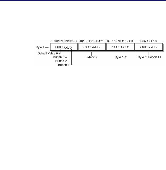
8.5 Report Example
The following Report descriptor defines an item with an Input report.
Usage Page (Generic Desktop), |
|
Usage (Mouse), |
|
Collection (Application), |
|
Usage (Pointer), |
|
Collection (Physical), |
|
Report ID (0A), |
;Make changes to report 0A |
Usage (X), Usage (Y), |
|
Logical Minimum (-127), |
;Report data values range from -127 |
Logical Maximum (127), |
;to 127 |
Report Size (8), Report Count (2), |
|
Input (Data, Variable, Relative), |
;Add 2 bytes of position data (X & Y) to report 0A |
Logical Minimum (0), |
;Report data values range from -127 |
Logical Maximum (1), |
;to 127 |
Report Count (3), Report Size (1), |
|
Usage Page (Button Page), |
|
Usage Minimum (1), |
|
Usage Maximum (3), |
|
6/277/00:
58 Device Class Definition for Human Interface Devices (HID) Version 1.11
Input |
(Data, Variable, Absolute), |
;Add |
2 |
bits |
(Button |
1, |
2 & 3) to report 0A |
Report Size (5), |
|
|
|
|
|
|
|
Input |
(Constant), |
;Add |
5 |
bits |
padding |
to |
byte align the report 0A |
End Collection,
End Collection
The Input report structure for the above device would look as follows.
The following table uses a keyboard with an integrated pointing device to demonstrate how to use two reports for a device with just one interface:
Item |
Usages |
Report ID |
Collection (Application) |
Keyboard |
|
Report ID (00) |
Modifier keys |
00 |
Input (Variable, Absolute) |
||
Output (Variable, Absolute) |
LEDs |
00 |
Input (Array, Absolute) |
Main keys |
00 |
End Collection |
Mouse |
|
Collection (Application) |
|
|
Report ID (01) |
Pointer |
|
Collection (Physical) |
01 |
|
Input (Variable, Relative) |
X, Y |
|
Input (Variable, Absolute) |
Button |
01 |
End Collection |
|
|
End Collection |
|
|
Note Only Input, Output, and Feature items (not Collection items) present data in a report. This example demonstrates multiple reports, however this interface would not be acceptable for a Boot Device (use separate interfaces for keyboards and mouse devices).
6/27/00:
Appendix A: Usage Tags |
59 |
Appendix A: Usage Tags
See the Universal Serial Bus HID Usage Tables document for a complete list of Usage Pages and Usage Tags, including key codes for keyboards.
Appendix B: Boot Interface Descriptors
The HID Subclass 1 defines two descriptors for Boot Devices. Devices may append additional data to these boot reports, but the first 8 bytes of keyboard reports and the first 3 bytes of mouse reports must conform to the format defined by the Boot Report descriptor in order for the data to be correctly interpreted by the BIOS. The report may not exceed 8 bytes in length. The BIOS will ignore any extensions to reports. These descriptors describe reports that the BIOS expects to see. However, since the BIOS does not actually read the Report descriptors, these descriptors do not have to be hard-coded into the device if an alternative report descriptor is provided. Instead, descriptors that describe the device reports in a USB-aware operating system should be included (these may or may not be the same). When the HID class driver is loaded, it will issue a Change Protocol, changing from the boot protocol to the report protocol after reading the boot interface’s Report descriptor.
B.1 Protocol 1 (Keyboard)
The following represents a Report descriptor for a boot interface for a keyboard.
Usage Page (Generic Desktop), |
|
Usage (Keyboard), |
|
Collection (Application), |
|
Report Size (1), |
|
Report Count (8), |
|
Usage Page (Key Codes), |
|
Usage Minimum (224), |
|
Usage Maximum (231), |
|
Logical Minimum (0), |
|
Logical Maximum (1), |
|
Input (Data, Variable, Absolute), |
;Modifier byte |
Report Count (1), |
|
Report Size (8), |
|
Input (Constant), |
;Reserved byte |
Report Count (5), |
|
Report Size (1), |
|
Usage Page (LEDs), |
|
Usage Minimum (1), |
|
Usage Maximum (5), |
|
6/277/00:

60 Device Class Definition for Human Interface Devices (HID) Version 1.11
Output (Data, Variable, Absolute), |
;LED report |
Report Count (1), |
|
Report Size (3), |
|
Output (Constant), |
;LED report padding |
Report Count (6), |
|
Report Size (8), |
|
Logical Minimum (0), |
|
Logical Maximum(255), |
|
Usage Page (Key Codes), |
|
Usage Minimum (0), |
|
Usage Maximum (255), |
|
Input (Data, Array), |
|
End Collection |
|
The following table represents the keyboard input report (8 bytes).
Byte |
Description |
0 |
Modifier keys |
1 |
Reserved |
2 |
Keycode 1 |
3 |
Keycode 2 |
4 |
Keycode 3 |
5 |
Keycode 4 |
6 |
Keycode 5 |
7 |
Keycode 6 |
Note Byte 1 of this report is a constant. This byte is reserved for OEM use. The BIOS should ignore this field if it is not used. Returning zeros in unused fields is recommended.
The following table represents the keyboard output report (1 byte).
Bit |
Description |
0 |
NUM LOCK |
1 |
CAPS LOCK |
2 |
SCROLL LOCK |
3 |
COMPOSE |
4 |
KANA |
5 to 7 |
CONSTANT |
Note The LEDs are absolute output items. This means that the state of each LED must be included in output reports (0 = off, 1 = on). Relative items would permit reports that affect only selected controls (0 = no change, 1= change).
6/27/00: