

42.6.1 Sdh network topologies
Once again traffic routing flexibility, its control and physical distribution within an SDH network, is one of the most important influences on the topologies proposed for the deployment of SDH equipment. The most obvious manifestations of this are the drop and insert ring topologies that are finding favour in the former junction areas of PTO networks. (See Figure 42.32.)
The idea behind a drop and insert ring is that the ring structure can give a high degree of protection against cable cuts etc. due to its potential for routing traffic either way round the ring. In fact, one of the biggest advantages, in control terms, of this topology is the limitation on the re-routeing possibilities for any traffic affected by a cable break. Anything more complicated than a simple clockwise/counter-clockwise routing decision requires up to date knowledge of a rather more extensive portion of an SDH network than just a simple ring. The nodes of such a ring are populated by drop and insert multiplexers which have a restricted traffic routing flexibility that is tailored to the requirements of a ring. This gives a relatively low cost ring implementation, which nevertheless, when viewed as a single entity, appears as a restricted form of a cross connect. The versatility of drop and insert rings also extends to drop and insert chains, which can be considered as a 'flattened' version of a conventional ring. (See Figure 42.33.) Beyond this, a ring can also be made from a chain of drop and insert multiplexers, whose ends have been joined by an SDH line system. The main problem with implementing this type of ring, at least in the junction area, is that the existing layout of cables and ducts usually takes the form of a star, which formerly linked the old analogue local exchanges to their district switching centre. In many cases, a partial physical ring can be created by a small extension of the existing cable pattern. This can be supplemented by creating a logical ring when existing cables are laid in a star arrangement, although this obviously affords less protection against cable breaks (See Figure 42.34.) Finally, it is sometimes possible to produce a physical ring by linking some of the ring nodes with microwave radio rather than optical fibre.
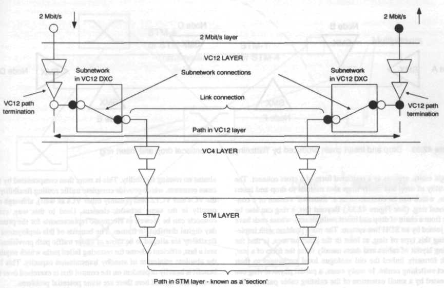
Figure 42.31 Use of two VC12 cross connects to produce a path within the VC12 layer
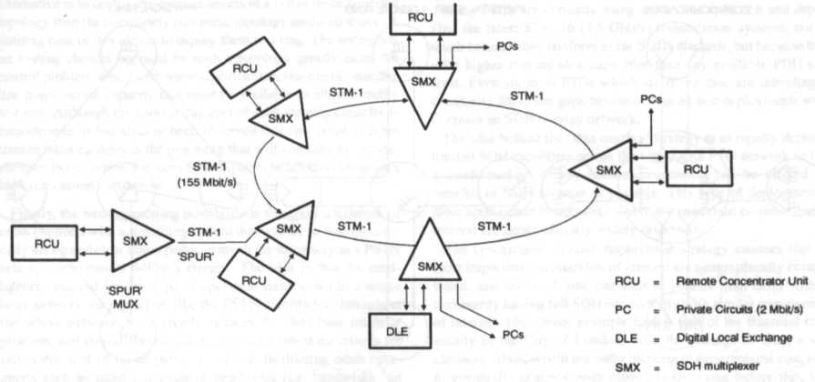
Figure 42.32 SDH multiplexers deployed in a drop and insert ring
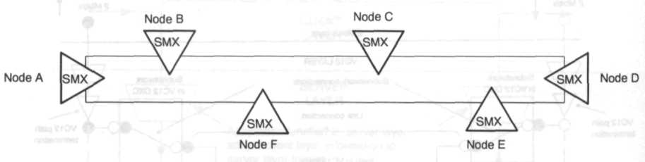
Figure 42.33 Drop and insert chain produced by flattening' a conventional drop and insert ring
Outside of the former junction areas, i.e. within the transmission core of the average PTO network, the normal topology advocated is that of a mesh of cross connects, interconnected by point to point transmission systems. (See Figure 42.35.) For this application, the SDH transmission systems, like their PDH counterparts, require the cross connects, which provide complete traffic routing flexibility at the VC4 and VC12 (and possibly other VCs as well), although not usually in the same network element. Used in this way, cross connects can be viewed as electronic replacements for the present day digital distribution frames. The benefits of this deployment of flexibility are alleged to be those of easier traffic path provisioning and a fast, efficient scheme for restoring failed paths which requires the absolute minimum of standby transmission capacity. This last benefit is heavily dependent on the control that is exercised over the cross connects, and here there are some potential problems.
The main problem is that of database integrity. With a network of meshed cross connects, when a transmission link fails, the path restoration action will usually involve re-routeing all the affected paths through several alternative cross connects. In order to do this efficiently the network control system must rapidly command simultaneous switching actions in all of these crossconnects, which usually implies that the control system has a pre-determined plan of action which is based on the spare bandwidth that is thought to be available on the relevant transmission links and cross connects. Unfortunately the integrity of the control systems database may have been compromised because of other recent reconfiguration. This problem escalates rapidly as the number of cross connects in a network increases.
There are several potential solutions to this problem. One is to simply not use the cross connects for protection against transmission failures, and, instead rely on transmission systems having 1 + 1 or 1:N protection. In this case the cross connects are used solely for off-line management of the network's transmission capacity. This is often call “Facilities Management” in North America. An alternative is to deploy the cross connects in a rather more bounded topology than the completely free mesh topology assumed above. A limiting case of this idea is to deploy them in a ring. The restriction on routing choices imposed by such a topology greatly cases the control problem, albeit with some significant increase in the standby line transmission capacity that must be available to allow a traffic re-route. Although the present day cost of such standby capacity is considerable, it has already been observed that raw point to point transmission capacity is the one thing that will continue to become cheaper, in real terms, for some time to come, hence this option may look increasingly attractive.
Finally, the most interesting possibility is to endow a network of cross connects with a signalling system that will allow it to dynamically set up and clear down paths, in much the same way as a PSTN sets up conventional 64kbit/s circuits. The idea is that the intelligence required for this type of operation resides, not in a single large network manager, but, like the PSTN, distributed throughout the whole network. This greatly reduces the data base integrity problem, and should operate quickly enough to meet the criteria for fast restoration of failed paths, as well as facilitating other operations such as rapid provision of bandwidth (i.e. bandwidth “on demand”) in response to requests from the client services of the SDH network.
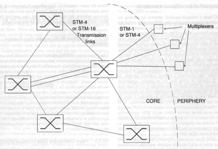
Figure 42.35 Example of core transmission network topology that relies on cross connects for flexibility