

42.4.6 Other sizes of vCs and payloads
The above description of the loading of a 2Mbil/s circuit into a VC-12, VC4 and hence into an STM-1, mentioned the existence of other sizes of VC. The complete family of VCs, together with their allowed multiplexing routes up to STM-1 are shown in Figure 42.14. So far mappings into these Synchronous Containers have been defined for all the common plesiochronous bit rates, together with few others, notably the l25Mbit/s FDDI signal. This latter mapping is somewhat wasteful of transmission bandwidth, as it loads the 125Mbit/s FDDI signal into a VC4 which has a payload capacity of around l49Mbit/s. It might be thought that this degree of inefficiency is more or less inevitable for any further type of signal whose bit rate does not correspond roughly with that of one of the existing Synchronous Containers. In fact, this is not necessarily so, because CCITT G.708 and G.709 contain provision for the concatenation of both TU2s and AU3s and AU4s.
As a hypothetical example, to illustrate the use of concatenated TU2s, an incoming service signal at, say l6Mbit/s, is mapped into a group of three VC2s, known collectively as a VC2-3c. (See Figure 42.18). These three VC2s are loaded into the VC4 with identical pointer values, and are subsequently transported, as a group, across the entire SDH network. The best current example of the use of this technique is in the area of video transmission, where a TV signal is digitally encoded at around 32Mbit/s, and subsequently loaded into a concatenated group of five VC2s (VC2-5c). This mapping allows up to four such video signals to be transported in a single VC4. If, instead, the normal mapping into a VC3 had been used, then only three video signals could have been accommodated within one VC4, hence a useful increase in efficiency by using concatenation.
So far, in this discussion, all the examples of a service rate signal being mapped into a Synchronous Container have assumed that the SDH network element makes no use of any structure that might be present in the service rate signal. In fact, this assumption is always true when the service rate signal is plesiochronous, however, because of the way the PSTN service is usually operated, with all of the switches running synchronously with one another, it was decided to endow SDH with a second class of mapping, known as byte synchronous mapping. Currently, the only byte synchronous mapping defined, is for a 2Mbit/s signal which has a G.704 frame structure (i.e. is byte orientated) and which is synchronous to the SDH network or, more precisely, synchronous with the network element which is mapping it into a Synchronous Container. In the course of a byte synchronous mapping, the SDH network element locks onto the incoming G.704 frame alignment word, and subsequently proceeds to load this, and every other byte in the G.704 frame, into predefined positions in the C12. (See Figure 42.19.)
This results in a situation whereby any channel of a 30 channel group can be easily located once the location of the VC12 POH has been established. The advantage of this mapping becomes apparent when considering two PSTN switches which are interconnected by several groups of 30 channels, that are transported over an SDH network. (See Figure 42 20.) It is easy for such a PSTN switch to operate as part of the SDH network by generating and byte synchronously loading its own VC12s, because it already knows the location of all 30 channels. It obviously does not need to search for frame alignment, as this too is already known. At the receiving PSTN switch, because the VC12s were mapped byte synchronously, there is also no need for a frame alignment operation, because this follows automatically once the phase of the VC12 is known. The removal of the G.704 frame alignment process not only leads to a reduction in gate count (and hence cost), but also reduces the delay associated with this operation. These advantages apply not just to the PSTN example given above, but, in fact, to any network where visibility and routing of individual 64 kbit/s channels is required, hence they could also apply to networks of PBXs or 64 kbit/s cross connects.
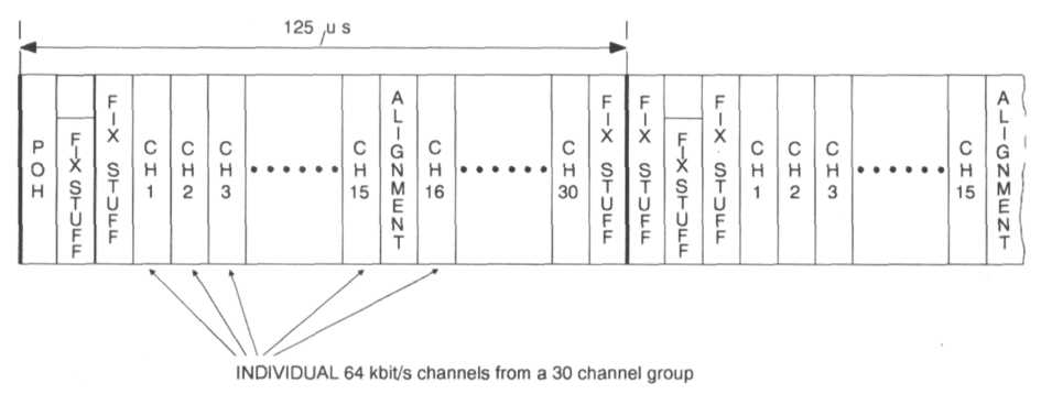
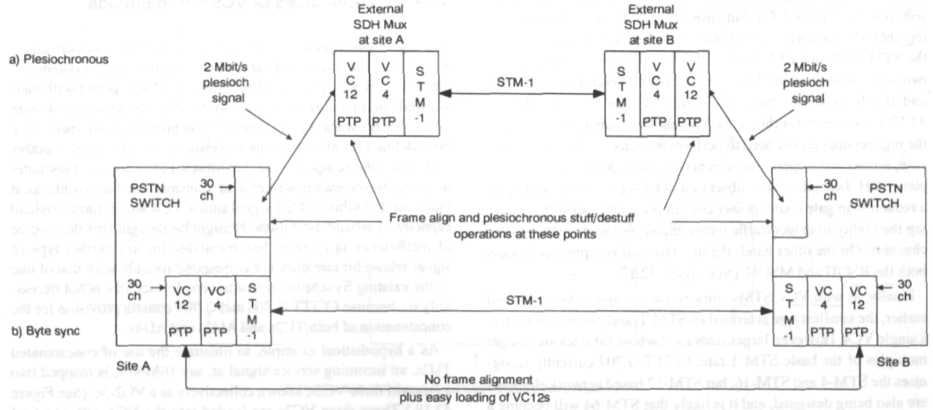
Figure 42.20 Comparison of plesiochronous and byte synchronous mappings of 30 channel groups between two PSTN switches