

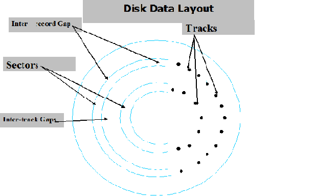
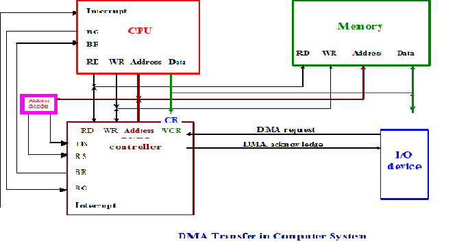
57. Describe the typical Disk data layout 29. Draw a scheme of dma Transfer
30. Which approaches can be taken… Multiple Interrupts – Sequential. This approach is nice and simple, as interrupts are handled in strict sequential order. The drawback of this approach is that it doesn’t take into account relative priority or time critical needs. Multiple Interrupts – Nested. This approach is to define priorities for interrupts and to allow an interrupt of higher priority (“estate”) to cause a lower-priority interrupt handler to be itself interrupted. Example.
Consider a system with 3 I/O devices:
a printer (priority 2);
a disk (priority 4);
a communication line (priority 5)
Let user program begins at t = 0. At t = 10, a printer interrupt occurs, user information is placed on the stack, and execution continues at the printer interrupt service routine (ISR). While this routine is still executing, at t = 15, a communication interrupt occurs. Since communication line has higher priority, the interrupt is honored, the printer ISR is interrupted.
What is the interconnection structure, and by which factors is it determined?
The way of connecting the various modules is called the interconnection structure.The interconnection structure is determined by character of exchange operations, which are specific for each module.
List the types of exchanges (input and output)
Memory: a memory module will consists of N words of equal length. Each word is assigned a unique numerical address (0, 1, …, N-1). A word of data can be read from or written into the memory. The nature of the operations is indicated by READ or WRITE control signals. The location for the operation is specified by an address.
I/O Module: It’s functionally similar to the memory (from internal point of view). There are two operations READ and WRITE. Further, an I/O module may control more than one external device. We can refer to each of the interfaces to an external device as a port and give each a unique address (e.g., 0, 1, 2.,…, M-1). In addition, there are external data paths for the input and output of data with an external device. Finally, an I/O module may be able to send interrupt signals to the CPU.
CPU: CPU reads in instructions and data, writes out data after processing, and uses control signals to control the overall operation of the system. It also receives interrupt signals.
Memory to CPU: The CPU reads an instruction or unit of data from memory.
CPU to Memory: The CPU writes a unit of data to memory.
I/O to CPU: The CPU reads data from I/O device via an I/O module.
CPU to I/O: The CPU sends data to the I/O device.
I/O to or from the Memory: For these two cases, an I/O module is allowed to exchange data directly with memory, without going through the CPU, using DMA.