1.The resonance method - application of a new nondestructive technique
The method of measuring the resonance frequencies of an object is comparatively new in the area of nondestructive testing techniques. In this method, waves produced by a short stress pulse and interferring in the specimen are analysed referring to their frequency spectrum. The resonance method is applied to structures that are not easy to access for testing, like concrete slabs and floors. We demonstrate that this method is capable of determining the thickness of these structures nondestructively and with sufficient precision. This method may be transferred to other materials at different expenditures. Besides, easy determination of stress wave velocity is possible, if the dimensions of the object are known.
First measurements of resonated waves produced by an impact on the surface of concrete structures were reported by Carino and Sansalone [l, 5, 6]. They developed the so-called "impact-echo method" in particular for the detection of ungrouted ducts and horizontal cracks in concrete. Although the phenomenon of waves reverberating between two discontinuity surfaces is well-known, until now a general transfer to material research is missing. An example is the geophysical prospection, where wave- forms produced by vibroseismic sweeps and explosions are evaluated not only in time domain, but the reverberation modes are also analysed in frequency domain. Fig. 1 from Berkhemer [2] shows schematically the different reverberating modes that are caused by the bedding in the upper earth crust.

Figure 1:"Multiples" caused by reverberations between different layers in the upper crust
Besides the detection of damages and inhomogeneities in an object, this technique is also capable of determining the dimensions of elements. This is a well-known problem, i. e. when making researches and expertises of damage at concrete buildings, especially when they are remote, like concrete pavements and catching basins. In these cases, today normally destructive tests are performed, using endoscopy in drill holes or examining drilling cores. In the conventional ultrasonic pulse-echo method, the stress pulse applied on the surface by an ultrasonic impactor is detected by an piezo- electric transducer. The return time of the wave reflected by an interface in the medium gives the information that is needed. In concrete, this method is failing due to the heterogeneity caused by the reinforcement and the large grain size of the Aggregate. Additionally, the wave field radiated by the impactor is disturbing the transducer, so that all further impulses are vanishing in the coda of the primary wave.
2. Physical background
The problem of wave propagation in concrete has already been discussed earlier [4]. Nevertheless, there are some new aspects with regard to the presented resonance method. Therefore, the physical background, already explained in detail by Carino and Sansalone and Koo et al., will be summarised for the present problem and illustrated by fig. 2.

Figure 2: Principle of resonant measurements.
The wave field radiated by the impactor 1 is propagating into the object along spherical wavefronts. After a short travel time t1 the direct wave meets the transducer a. Depending on the distance between impactor and transducer, at a later time also the background echo reaches the transducer. However, this signal is vanishing in the seismic recording of the primary wave due to the strong attenuation in concrete (15-20 dB/m). Besides, a waveform with period T (wavelength L1 = double object thickness 2d) is developing, consisting of a constructive interference. This means, finally a stationary wave is dominating the recording, showing a rather low-frequency signal with frequency Fr. An analysis of the time signal by a fast fourier transform shows the frequency spectrum of the primary wave plus the resonance modes± according to the thickness of the object. This relation yields the following expression:
Equation 1 : d = vp/2 *Fr
In the case of additional discontinuities in the medium like spalls or horizontal flaws, the spectrum shows indeed additional maxima that are more or less clear. However, normally the main peak in the resultant spectrum is due to the background echo (discontinuity concrete-air).
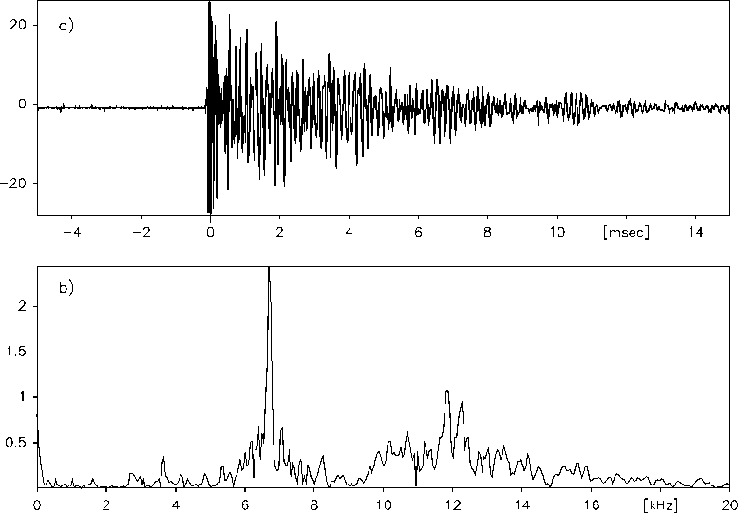
This fact is illustrated in fig. 3. According to the method we will describe below, a wave has been applied on the surface of a concrete slab. This wave was detected with a piezo-transducer at a distance of 5 cm. Fig. 3 a) shows the complete signal in the time domain. The signal decays after approximately 20 ms. The transformation of this signal into the frequency domain² shows fig. 3 b). The main maximum in the amplitude spectrum near 6,7 kHz is corresponding (using eq. 1) to a thickness of the concrete slab of 30 cm and a wave velocity of 4020 m/s. The period of this wave is according to twice the object thickness.