

EN 1990.2002 Basis of structural design
.pdfLicensed copy:UNIVERSITY OF PORTSMOUTH, 12/07/2004, Uncontrolled Copy, © BSI
|
|
|
|
EN 1990:2002 (E) |
||
Table A1.1 - Recommended values of factors for buildings |
||||||
|
|
|
|
|
|
|
Action |
0 |
|
1 |
|
2 |
|
Imposed loads in buildings, category (see |
|
|
|
|
|
|
EN 1991-1-1) |
|
|
|
|
|
|
Category A : domestic, residential areas |
0,7 |
|
0,5 |
|
0,3 |
|
Category B : office areas |
0,7 |
|
0,5 |
|
0,3 |
|
Category C : congregation areas |
0,7 |
|
0,7 |
|
0,6 |
|
Category D : shopping areas |
0,7 |
|
0,7 |
|
0,6 |
|
Category E : storage areas |
1,0 |
|
0,9 |
|
0,8 |
|
Category F : traffic area, |
|
|
|
|
|
|
vehicle weight 30kN |
0,7 |
|
0,7 |
|
0,6 |
|
Category G : traffic area, |
|
|
|
|
|
|
30kN < vehicle weight 160kN |
0,7 |
|
0,5 |
|
0,3 |
|
Category H : roofs |
0 |
|
0 |
|
0 |
|
Snow loads on buildings (see EN 1991-1-3)* |
|
|
|
|
|
|
Finland, Iceland, Norway, Sweden |
0,70 |
|
0,50 |
|
0,20 |
|
Remainder of CEN Member States, for sites |
0,70 |
|
0,50 |
|
0,20 |
|
located at altitude H > 1000 m a.s.l. |
|
|
|
|
|
|
Remainder of CEN Member States, for sites |
0,50 |
|
0,20 |
|
0 |
|
located at altitude H 1000 m a.s.l. |
|
|
|
|
|
|
Wind loads on buildings (see EN 1991-1-4) |
0,6 |
|
0,2 |
|
0 |
|
Temperature (non-fire) in buildings (see EN |
0,6 |
|
0,5 |
|
0 |
|
1991-1-5) |
|
|
|
|
|
|
NOTE The values may be set by the National annex. |
|
|
|
|
||
* For countries not mentioned below, see relevant local conditions. |
|
|
|
|
||
A1.3 Ultimate limit states
A1.3.1 Design values of actions in persistent and transient design situations
(1) The design values of actions for ultimate limit states in the persistent and transient design situations (expressions 6.9a to 6.10b) should be in accordance with Tables A1.2(A) to (C).
NOTE The values in Tables A1.2 ((A) to (C)) can be altered e.g. for different reliability levels in the National annex (see Section 2 and Annex B).
(2)In applying Tables A1.2(A) to A1.2(C) in cases when the limit state is very sensitive to variations in the magnitude of permanent actions, the upper and lower characteristic values of actions should be taken according to 4.1.2(2)P.
(3)Static equilibrium (EQU, see 6.4.1) for building structures should be verified using the design values of actions in Table A1.2(A).
(4)Design of structural members (STR, see 6.4.1) not involving geotechnical actions should be verified using the design values of actions from Table A1.2(B).
(5)Design of structural members (footings, piles, basement walls, etc.) (STR) involving geotechnical actions and the resistance of the ground (GEO, see 6.4.1) should be verified using one of the following three approaches supplemented, for geotechnical actions and resistances, by EN 1997 :
49
Licensed copy:UNIVERSITY OF PORTSMOUTH, 12/07/2004, Uncontrolled Copy, © BSI
EN 1990:2002 (E)
–Approach 1: Applying in separate calculations design values from Table A1.2(C) and Table A1.2(B) to the geotechnical actions as well as the other actions on/from the structure. In common cases, the sizing of foundations is governed by Table A1.2(C) and the structural resistance is governed by Table A1.2(B) ;
NOTE In some cases, application of these tables is more complex, see EN 1997.
–Approach 2 : Applying design values from Table A1.2(B) to the geotechnical actions as well as the other actions on/from the structure ;
–Approach 3 : Applying design values from Table A1.2(C) to the geotechnical actions and, simultaneously, applying partial factors from Table A1.2(B) to the other actions on/from the structure,
NOTE The use of approaches 1, 2 or 3 is chosen in the National annex.
(6)Overall stability for building structures (e.g. the stability of a slope supporting a building) should be verified in accordance with EN 1997.
(7)Hydraulic and buoyancy failure (e.g. in the bottom of an excavation for a building structure) should be verified in accordance with EN 1997.
50

Licensed copy:UNIVERSITY OF PORTSMOUTH, 12/07/2004, Uncontrolled Copy, © BSI
EN 1990:2002 (E)
Table A1.2(A) - Design values of actions (EQU) (Set A)
Persistent |
Permanent actions |
Leading |
Accompanying variable |
|||
and |
|
|
variable |
|
actions |
|
transient |
|
|
action (*) |
|
|
|
design |
|
|
|
|
|
|
situations |
|
|
|
|
|
|
|
Unfavourable |
Favourable |
|
Main |
|
Others |
|
|
|
|
(if any) |
|
|
(Eq. 6.10) |
Gj,supGkj,sup |
Gj,infGkj,inf |
Q,1 Qk,1 |
|
|
Q,i 0,iQk,i |
|
|
|
|
|
|
|
(*) Variable actions are those considered in Table A1.1
NOTE 1 The values may be set by the National annex. The recommended set of values for are :
Gj,sup = 1,10
Gj,inf = 0,90
Q,1 = 1,50 where unfavourable (0 where favourable)
Q,i = 1,50 where unfavourable (0 where favourable)
NOTE 2 In cases where the verification of static equilibrium also involves the resistance of structural members, as an alternative to two separate verifications based on Tables A1.2(A) and A1.2(B), a combined verification, based on Table A1.2(A), may be adopted, if allowed by the National annex, with the following set of recommended values. The recommended values may be altered by the National annex.
Gj,sup = 1,35
Gj,inf = 1,15
Q,1 = 1,50 where unfavourable (0 where favourable)
Q,i = 1,50 where unfavourable (0 where favourable)
provided that applying Gj,inf = 1,00 both to the favourable part and to the unfavourable part of permanent actions does not give a more unfavourable effect.
51

Licensed copy:UNIVERSITY OF PORTSMOUTH, 12/07/2004, Uncontrolled Copy, © BSI
EN 1990:2002 (E)
Table A1.2(B) - Design values of actions (STR/GEO) (Set B)
Persistent |
Permanent actions |
Leading |
Accompanying |
||
and |
|
|
variable |
variable actions (*) |
|
transient |
|
|
action |
|
|
design |
|
|
|
|
|
situations |
|
|
|
|
|
|
Unfavourable |
Favourable |
|
Main |
Others |
|
|
|
|
(if any) |
|
(Eq. 6.10) |
Gj,supGkj,sup |
Gj,infGkj,inf |
Q,1Qk,1 |
|
Q,i 0,iQk,i |
|
|
|
|
|
|
Persistent |
Permanent actions |
Leading |
Accompanying |
||
and |
|
|
variable |
variable actions (*) |
|
transient |
|
|
action (*) |
|
|
design |
|
|
|
|
|
situations |
|
|
|
|
|
|
Unfavourable |
Favourable |
Action |
Main |
Others |
|
|
|
|
|
|
(Eq. 6.10a) |
Gj,supGkj,sup |
Gj,infGkj,inf |
|
Q,1 0,1Qk,1 |
Q,i 0,iQk,i |
|
|
|
|
|
|
(Eq. 6.10b) |
Gj,supGkj,sup |
Gj,infGkj,inf |
Q,1Qk,1 |
|
Q,i 0,iQk,i |
|
|
|
|
|
|
(*) Variable actions are those considered in Table A1.1
NOTE 1 The choice between 6.10, or 6.10a and 6.10b will be in the National annex. In case of 6.10a and 6.10b, the National annex may in addition modify 6.10a to include permanent actions only.
NOTE 2 The and values may be set by the National annex. The following values for and are recommended when using expressions 6.10, or 6.10a and 6.10b.
Gj,sup = 1,35Gj,inf = 1,00
Q,1 = 1,50 where unfavourable (0 where favourable)Q,i = 1,50 where unfavourable (0 where favourable)= 0,85 (so that Gj,sup = 0,85 1,35 1,15).
See also EN 1991 to EN 1999 for values to be used for imposed deformations.
NOTE 3 The characteristic values of all permanent actions from one source are multiplied by G,sup if the total resulting action effect is unfavourable and G,inf if the total resulting action effect is favourable. For example, all actions originating from the self weight of the structure may be considered as coming from one source ; this also applies if different materials are involved.
NOTE 4 For particular verifications, the values for G and Q may be subdivided into g and q and the model uncertainty factor Sd. A value of Sd in the range 1,05 to 1,15 can be used in most common cases and can be modified in the National annex.
52
Licensed copy:UNIVERSITY OF PORTSMOUTH, 12/07/2004, Uncontrolled Copy, © BSI
EN 1990:2002 (E)
Table A1.2(C) - Design values of actions (STR/GEO) (Set C)
Persistent |
Permanent actions |
Leading |
Accompanying variable |
||
and |
|
|
variable |
actions (*) |
|
transient |
|
|
action (*) |
|
|
design |
|
|
|
|
|
situation |
|
|
|
|
|
|
Unfavourable |
Favourable |
|
Main (if any) |
Others |
|
|
|
|
|
|
(Eq. 6.10) |
Gj,supGkj,sup |
Gj,infGkj,inf |
Q,1 Qk,1 |
|
Q,i 0,iQk,i |
|
|
|
|
|
|
(*) Variable actions are those considered in Table A1.1
NOTE The values may be set by the National annex. The recommended set of values for are :
Gj,sup = 1,00Gj,inf = 1,00
Q,1 = 1,30 where unfavourable (0 where favourable)
Q,i = 1,30 where unfavourable (0 where favourable)
A1.3.2 Design values of actions in the accidental and seismic design situations
(1) The partial factors for actions for the ultimate limit states in the accidental and seismic design situations (expressions 6.11a to 6.12b) should be 1,0. values are given in Table A1.1.
NOTE For the seismic design situation see also EN 1998.
Table A1.3 - Design values of actions for use in accidental and seismic combinations of actions
Design |
Permanent actions |
Leading |
Accompanying |
|
||
situation |
|
|
accidental |
variable actions (**) |
||
|
|
|
or seismic |
|
|
|
|
|
|
action |
|
|
|
|
Unfavourable |
Favourable |
|
Main (if any) |
Others |
|
|
|
|
|
|
|
|
Accidental (*) |
Gkj,sup |
Gkj,inf |
Ad |
11 or |
2,i |
Qk,i |
(Eq. 6.11a/b) |
|
|
|
21Qk1 |
|
|
|
|
|
|
|
|
|
Seismic |
Gkj,sup |
Gkj,inf |
IAEk or AEd |
|
2,i |
Qk,i |
(Eq. 6.12a/b) |
|
|
|
|
|
|
(*) In the case of accidental design situations, the main variable action may be taken with its frequent or, as in seismic combinations of actions, its quasi-permanent values. The choice will be in the National annex, depending on the accidental action under consideration. See also EN 1991-1-2.
(**) Variable actions are those considered in Table A1.1.
53
Licensed copy:UNIVERSITY OF PORTSMOUTH, 12/07/2004, Uncontrolled Copy, © BSI
EN 1990:2002 (E)
A1.4 Serviceability limit states
A1.4.1 Partial factors for actions
(1) For serviceability limit states the partial factors for actions should be taken as 1,0 except if differently specified in EN 1991 to EN 1999.
Table A1.4 - Design values of actions for use in the combination of actions
Combination |
Permanent actions Gd |
Variable actions Qd |
|
||
|
Unfavourable |
Favourable |
Leading |
Others |
|
|
|
|
|
|
|
Characteristic |
Gkj,sup |
Gkj,inf |
Qk,1 |
0,iQk,i |
|
Frequent |
Gkj,sup |
Gkj,inf |
1,1Qk,1 |
2,iQk,i |
|
|
|||||
Quasi-permanent |
Gkj,sup |
Gkj,inf |
|
|
|
|
2,1Qk,1 |
2,iQk,i |
|||
|
|
|
|
|
|
A1.4.2 Serviceability criteria
(1)Serviceability limit states in buildings should take into account criteria related, for example, to floor stiffness, differential floor levels, storey sway or/and building sway and roof stiffness. Stiffness criteria may be expressed in terms of limits for vertical deflections and for vibrations. Sway criteria may be expressed in terms of limits for horizontal displacements.
(2)The serviceability criteria should be specified for each project and agreed with the client.
NOTE The serviceability criteria may be defined in the National annex.
(3)P The serviceability criteria for deformations and vibrations shall be defined :
–depending on the intended use ;
–in relation to the serviceability requirements in accordance with 3.4 ;
–independently of the materials used for supporting structural member.
A1.4.3 Deformations and horizontal displacements
(1)Vertical and horizontal deformations should be calculated in accordance with EN 1992 to EN 1999, by using the appropriate combinations of actions according to expressions (6.14a) to (6.16b) taking into account the serviceability requirements given in 3.4(1). Special attention should be given to the distinction between reversible and irreversible limit states.
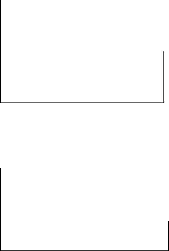
(2)Vertical deflections are represented schematically in Figure. A1.1.
54
Licensed copy:UNIVERSITY OF PORTSMOUTH, 12/07/2004, Uncontrolled Copy, © BSI
EN 1990:2002 (E)
|
Figure A1.1 - Definitions of vertical deflections |
Key : |
|
wc |
Precamber in the unloaded structural member |
w1 |
Initial part of the deflection under permanent loads of the relevant combination of |
|
actions according to expressions (6.14a) to (6.16b) |
w2 |
Long-term part of the deflection under permanent loads |
w3 |
Additional part of the deflection due to the variable actions of the relevant combi- |
|
nation of actions according to expressions (6.14a) to (6.16b) |
wtot |
Total deflection as sum of w1 , w2 , w3 |
wmax |
Remaining total deflection taking into account the precamber |
(3) If the functioning or damage of the structure or to finishes, or to non-structural members (e.g. partition walls, claddings) is being considered, the verification for deflection should take account of those effects of permanent and variable actions that occur after the execution of the member or finish concerned.
NOTE Guidance on which expression (6.14a) to (6.16b) to use is given in 6.5.3 and EN 1992 to EN 1999.
(4)If the appearance of the structure is being considered, the quasi-permanent combination (expression 6.16b) should be used.
(5)If the comfort of the user, or the functioning of machinery are being considered, the verification should take account of the effects of the relevant variable actions.
(6)Long term deformations due to shrinkage, relaxation or creep should be considered where relevant, and calculated by using the effects of the permanent actions and quasipermanent values of the variable actions.
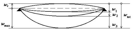
(7)Horizontal displacements are represented schematically in Figure A1.2.
55

EN 1990:2002 (E)
Licensed copy:UNIVERSITY OF PORTSMOUTH, 12/07/2004, Uncontrolled Copy, © BSI
|
Figure A1.2 - Definition of horizontal displacements |
Key : |
|
u |
Overall horizontal displacement over the building height H |
ui |
Horizontal displacement over a storey height Hi |
A1.4.4 Vibrations
(1) To achieve satisfactory vibration behaviour of buildings and their structural members under serviceability conditions, the following aspects, amongst others, should be considered :
a)the comfort of the user;
b)the functioning of the structure or its structural members (e.g. cracks in partitions, damage to cladding, sensitivity of building contents to vibrations).
Other aspects should be considered for each project and agreed with the client.
(2)For the serviceability limit state of a structure or a structural member not to be exceeded when subjected to vibrations, the natural frequency of vibrations of the structure or structural member should be kept above appropriate values which depend upon the function of the building and the source of the vibration, and agreed with the client and/or the relevant authority.
(3)If the natural frequency of vibrations of the structure is lower than the appropriate value, a more refined analysis of the dynamic response of the structure, including the consideration of damping, should be performed.
NOTE For further guidance, see EN 1991-1-1, EN 1991-1-4 and ISO 10137.
(4) Possible sources of vibration that should be considered include walking, synchronised movements of people, machinery, ground borne vibrations from traffic, and wind actions. These, and other sources, should be specified for each project and agreed with the client.
56
Licensed copy:UNIVERSITY OF PORTSMOUTH, 12/07/2004, Uncontrolled Copy, © BSI
EN 1990:2002 (E)
Annex B
(informative)
Management of Structural Reliability for Construction Works
B1 Scope and field of application
(1) This annex provides additional guidance to 2.2 (Reliability management) and to appropriate clauses in EN 1991 to EN 1999.
NOTE Reliability differentiation rules have been specified for particular aspects in the design Eurocodes, e.g. in EN 1992, EN 1993, EN 1996, EN 1997 and EN 1998.
(2) The approach given in this Annex recommends the following procedures for the management of structural reliability for construction works (with regard to ULSs, excluding fatigue) :
a)In relation to 2.2(5)b, classes are introduced and are based on the assumed consequences of failure and the exposure of the construction works to hazard. A procedure for allowing moderate differentiation in the partial factors for actions and resistances corresponding to the classes is given in B3.
NOTE Reliability classification can be represented by indexes (see Annex C) which takes account of accepted or assumed statistical variability in action effects and resistances and model uncertainties.
b) In relation to 2.2(5)c and 2.2(5)d, a procedure for allowing differentiation between various types of construction works in the requirements for quality levels of the design and execution process are given in B4 and B5.
NOTE Those quality management and control measures in design, detailing and execution which are given in B4 and B5 aim to eliminate failures due to gross errors, and ensure the resistances assumed in the design.
(3) The procedure has been formulated in such a way so as to produce a framework to allow different reliability levels to be used, if desired.
B2 Symbols
In this annex the following symbols apply.
KFI |
Factor applicable to actions for reliability differentiation |
|
Reliability index |
57
Licensed copy:UNIVERSITY OF PORTSMOUTH, 12/07/2004, Uncontrolled Copy, © BSI
EN 1990:2002 (E)
B3 Reliability differentiation
B3.1 Consequences classes
(1)For the purpose of reliability differentiation, consequences classes (CC) may be established by considering the consequences of failure or malfunction of the structure as given in Table B1.
Table B1 - Definition of consequences classes
Consequences |
Description |
Examples of buildings and civil |
Class |
|
engineering works |
CC3 |
High consequence for loss of human |
Grandstands, public buildings where |
|
life, or economic, social or |
consequences of failure are high (e.g. a |
|
environmental consequences very great |
concert hall) |
CC2 |
Medium consequence for loss of human |
Residential and office buildings, public |
|
life, economic, social or environmental |
buildings where consequences of failure |
|
consequences considerable |
are medium (e.g. an office building) |
CC1 |
Low consequence for loss of human life, |
Agricultural buildings where people do |
|
and economic, social or environmental |
not normally enter (e.g. storage |
|
consequences small or negligible |
buildings), greenhouses |
(2)The criterion for classification of consequences is the importance, in terms of consequences of failure, of the structure or structural member concerned. See B3.3
(3)Depending on the structural form and decisions made during design, particular members of the structure may be designated in the same, higher or lower consequences class than for the entire structure.
NOTE At the present time the requirements for reliability are related to the structural members of the construction works.
B3.2 Differentiation by values
(1)The reliability classes (RC) may be defined by the reliability index concept.
(2)Three reliability classes RC1, RC2 and RC3 may be associated with the three consequences classes CC1, CC2 and CC3.
(3)Table B2 gives recommended minimum values for the reliability index associated with reliability classes (see also annex C).
58