

ssd-2 Lecture+2
.pdfAndrey V. Andreev a.v.andreev@gmail.com

1.Data representation
1.Decimal
2.Binary
3.Hexadecimal
2.Hardware Systems
1.Processor and Memory
2.Processor Basics
3.Type of memory
4.Peripherals
5.Connecting Peripherals
6.Buses
7.Input/Output Devices

Data can be represented electronically with electrical components being on or off.
On and off states can be represented using digits 0s and 1s. For example:
◦0: Off state
◦1: On state
Thus, data can be represented digitally using digits 0 and 1 (binary digits).
Each binary digit is called a bit.
Eight bits equal to one byte.

Decimal: base 10 (digits 0-9)
Binary: base 2 (digits 0-1)
Hexadecimal: base16 (digits 0-9 and A-F)
◦Each hexadecimal digit represents four binary places.
◦Hex digit can be used as shorthand for binary notation
One Hex digit |
four bits |
One byte = 8 bits |
two Hex digits |

The formula can be used to convert a number in any numbering system to decimal.
◦dp(b)p + dp-1(b)p-1 + . . . + d0(b)0
◦where p is the place, b is the base, dp is the digit in the highest place in the number, and dp-1 is the next highest place in the number, and so on.
For converting hexadecimal into decimal use the formula:
◦p(b)p + dp-1(b)p-1 + . . . + d0(b)0
◦where dp is the digit in the highest place in the number, and dp-1 is the next highest place in the number, and so on. b is the base and p is the value of the highest place.
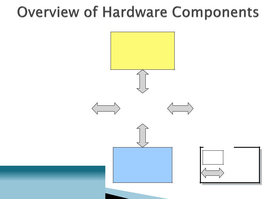
Microprocessor
(executes instructions)
|
|
|
|
Main Memory |
Storage Devices |
|
Chipset |
|
(temporarily stores data |
(permanently store data |
|
|
and program instructions |
|
|
(controls data flow) |
|
||
and application programs) |
|
|
while the computer |
|
|
|
|
||
|
|
|
|
is running) |
|
|
|
|
|
Legend
Components
Peripherals
(input/output)
Data Path

The microprocessor sends instructions to the storage devices (via the chipset) requesting the specified file to be loaded into main memory.
The storage devices send the file through the chipset to main memory.
The microprocessor fetches the file contents from main memory.
|
The microprocessor sends the |
Microprocessor |
|
display data to the monitor via |
(executes instructions) |
|
the chipset. |
|
Storage Devices
(permanently store data and application programs)
1 |
4 |
3 |
2 |
|
|
|
|
|
|
|
Chipset |
Peripherals
(input/output)
Main Memory
(temporarily stores data and program instructions while the computer
is running)
Legend |
Components |
Data Path |

A. Motherboard
B. Power supply
H. Disk drives
C. Microprocessor (underneath a cooling fan)
 G. IDE cable
D. Expansion slot
E. Expansion card
F. Chipset

Memory
Let R = X + Y
Number 1 (X)
Number 2 (Y)
Result R
Step 4. Result is stored back in memory.
Step 1. Control unit |
Control Unit |
fetches instruction |
Step 2. Control unit interprets the instruction and sends the 2 numbers to be added into the appropriate registers in the ALU.
ALU |
|
Register 1 |
Register 2 |
(contains Number 1) |
(contains Number 2) |
Accumulator |
|
(Result of Number 1 + |
|
Number 2) |
|
Step 3. Control unit executes the instruction by directing the ALU to add the 2 numbers in the registers 1 and 2 then store the result in the accumulator.

Storage Devices
(permanently store data and application programs)
Microprocessor
CPU
(ALU, Registers, Control unit)
L1 cache
L2 cache
(usually on CPU)
Chipset
(controls data flow)
Main Memory
(temporarily stores data and program instructions while the computer
is running)
Legend
Components
Peripherals
(input/output)
Data Path