

2. Wing
2.1. General
The main function of the wings is to sustain the weight of the airplane in the flight. The magnitude of the lift depends chiefly on four factors, namely: the speed of the flight; the surface area of the wing; the density of the air; the coefficient of lift.
One may express the lift in the following way:
L=cLV2/2* S;
where:L- lift; - density of the air; V – velocity of resultant wind; cL - coefficient of lift.
The value of the coefficient of lift depends on the angle of attack and on the aerofoil section.
Airfoil geometry can be characterized by the coordinates of the upper and lower surface. It is often summarized by a few parameters such as: maximum thickness, maximum camber, position of max thickness, position of max camber, and nose radius (Fig. 2.1).

Fig. 2.1. Geometric parameters of an airfoil
The angle of attack is the angle between the airfoil chord and the velocity of the resultant wind.
The front portion of a wing is termed the leading edge, and the rear portion is called the trailing edge.
The center of pressure is the point at which the resultant force on the aerofoil cuts the chord.
The chord is the distance between the leading edge and the trailing edge of the wing.
The drag may be written:
X=cD V2/2* S;
where cD is drag coefficient, which is also depends mainly on the angle of attack and airfoil section.
The greater the ratio of lift to drag, the more efficient is the wing aerodynamically.
The design of a wing depends upon such factors as the size, weight, and use of the airplane, desired speed, rate of climb, etc.
The airplane may have parasol, low-wing, mid-wing and high-wing constructions.
An airplane with one set of wing is called a monoplane. Monoplanes most generally used have cantilever wing. The airplane with two wings is called biplane.
The distance between the upper and lower wings (for biplane, for example AN-2) is called the gap.
The shape of the wing may be rectangular, triangular, elliptical and swept back.
Modern high speed aircraft have sweepback wings. Sweepback is the angle between the leading edge of the wing and perpendicular to the longitudinal centre line of the aircraft or the angle between the line of the quarter of chords and perpendicular to the longitudinal centre line of the aircraft.
The dimension over the extreme tips of the wing is called a span.
Some wing parameters presented on Fig. 2.2.
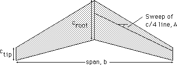
Fig. 2.2. Wing Design Parameters
An important characteristic of the wing is an aspect ratio. If the plan form of the wing is rectangular, the aspect ratio is thus equal to l/b, where l is the span, and b is the length of the constant chord. If the wing is tapered, the aspect ratio is defined as a ratio of the span to the mean geometric chord. The mean geometric chord is equal to the area divided by the span, i.e. s/l and the aspect ratio is therefore equal to l2/S.
The greater the aspect ratio of the wing, the more efficient is the wing aerodynamically.
The angle between the outer wing and a horizontal plane is called the dihedral angle of the wing.
The angle of incidence is the angle between the longitudinal axis of the airplane and the chord of the wing.
A wing designed for efficient high-speed flight is often quite different from one designed solely for take-off and landing. Take-off and landing distances are strongly influenced by aircraft stalling speed, with lower stall speeds requiring lower acceleration or deceleration and correspondingly shorter field lengths. It is always possible to reduce stall speed by increasing wing area, but it is not desirable to cruise with hundreds of square feet of extra wing area (and the associated weight and drag), area that is only needed for a few minutes.
It is also possible to reduce stalling speed by increasing wing CLmax. One can design a wing airfoil that compromises cruise efficiency to obtain a good CLmax , but it is usually more efficient to include movable leading and/or trailing edges so that one may obtain good high speed performance while achieving a high CLmax at take-off and landing. The primary goal of a high lift system is a high CLmax; however, it may also be desirable to maintain low drag at take-off, or high drag on approach. It is also necessary to do this with a system that has low weight and high reliability.
This is generally achieved by incorporating some form of trailing edge flap and perhaps a leading edge device such as a slat.
In the design of a double-slotted flap and slat system (a 4-element airfoil) some of the increase in CLmax is associated with an increase in chord length (Fowler motion) provided by motion along the flap track or by a rotation axis that is located below the wing (Fig. 2.3).

Fig. 2.3. Double-Slotted Flap and Slat System
Modern high lift systems are often quite complex with many elements and multi-bar linkages. Current practice has been to simplify the flap system and double (or even single) slotted systems are often preferred.
Flaps change the airfoil pressure distribution, increasing the camber of the airfoil and allowing more of the lift to be carried over the rear portion of the section. If the maximum lift coefficient is controlled by the height of the forward suction peak, the flap permits more lift for a given peak height. Flaps also increase the lift at a given angle of attack, important for aircraft which are constrained by ground angle limits.
Slotted flaps achieve higher lift coefficients than plain or split flaps because the boundary layer that forms over the flap starts at the flap leading edge and is "healthier" than it would have been if it had traversed the entire forward part of the airfoil before reaching the flap. The forward segment also achieves a higher Clmax than it would without the flap because the pressure at the trailing edge is reduced due to interference, and this reduces the adverse pressure gradient in this region.
The favorable effects of a slotted flap on Clmax was known early in the development of high lift systems. That a 2-slotted flap is better than a single-slotted flap and that a triple-slotted flap achieved even higher Cl's suggests that one might try more slots. Handley Page did this in the 1920's (Fig..2.4). Tests showed a Clmax of almost 4.0 for a 6-slotted airfoil.

Fig. 2.4. Multi-element section from 1921
Leading edge devices such as nose flaps, Kruger flaps, and slats reduce the pressure peak near the nose by changing the nose camber (Fig.. 2.5). Slots and slats permit a new boundary layer to start on the main wing portion, eliminating the detrimental effect of the initial adverse gradient.

Fig. 2.5. Leading Edge Devices
Slats operate rather differently from flaps in that they have little effect on the lift at a given angle of attack. Rather, they extend the range of angles over which the flow remains attached.
Today computational fluid dynamics is used to design these complex systems; however, the prediction of CLmax by direct computation is still difficult and unreliable. Wind tunnel tests are also difficult to interpret due to the sensitivity of CLmax to Reynolds number and even freestream turbulence levels.
Structural members of the wings are spars, stringers, ribs, skin.
Spar runs along the length of the wing from the fuselage to the tip of the wing. Commonly wing design have one, two or three spars.
In the design of light aircraft with fabric skin spars carry main part of the load, but more usually all wing members carry significant part of loads. Such structures have so called “stressed skin”.
Perpendicular to the spar are a series of ribs. The ribs are placed at frequent intervals to develop the wing contour.
There are two main kinds of ribs: normal and reinforced. Normal ribs withstand air loads and form airfoil cross section. Reinforced ribs withstand concentrated loads, for example loads, transmitted from landing gear, engines, etc.
Stringers are fixed to the inside of the skin. Stringers are riveted parallel to and between the spars. The heads of rivets are being flushed on the inside. The thickened portions of cross section improve the stability of the stringer under the compression.
Stringers may be manufactured by extrusion or bending from metal sheet.
Conventional materials for wing members manufacturing are aluminum alloys, such as D-16, V-95 of Ukrainian or Russian production and 2024T3, 7075T6 of western manufacturing. Some elements of modern aircraft are made of composite materials.
The larger compartments of wings contain, or are themselves used as fuel tanks.