

Automatic Tools for Design Hardening
Celia López-Ongil, Luis Entrena, Mario García-Valderas, Marta Portela-García
Electronic Technology Department. Carlos III University of Madrid Avda. de la Universidad, 30. 28911 Leganés (Madrid) Spain
{celia, entrena, mgvalder, mportela}@ing.uc3m.es
Abstract. Historically, there has been a lack of CAD tools for the design of online testable circuits. As a consequence, the design of on-line testable circuits is currently being made manually to a large extent. In this paper we detailed an academic tool for the automatic insertion of fault-tolerant structures in designs described at Register Transfer Level (RTL). With this tool, a fault-tolerant version of the design can be automatically produced according to the user specifications. The resulting fault-tolerant design is also described at RTL and can be simulated and synthesized with commercial tools. Examples are shown to demonstrate the capabilities of this approach.
1. Introduction
Traditionally, on-line testing technology has been restricted to few application domains. The area and performance penalties introduced by on-line testing were only accepted in order to meet high reliability requirements in safety critical applications. The relatively small number of such applications did not make attractive for CAD vendors the development of tools specific to the design of on-line testable circuits. As a matter of fact, on-line testable circuits are being designed manually to a large extent. This requires large design efforts that affect negatively design productivity and time- to-market.
With the widespread use of Hardware Description Languages (HDLs), most designs are usually started at the Register Transfer Level (RTL) supported by these languages and synthesis tools. Once the design has been validated by simulation, logic synthesis and place and route are generally used to obtain the lower level models of the design in an automatic way. The increase in the abstraction level, supported by automatic CAD tools, has allowed unprecedented productivity and shorter development times in the design of ICs.
The design of an on-line testable circuit is usually accomplished by introducing fault-tolerant structures in a previously designed circuit. Within the current HDLbased methodologies, the insertion of fault-tolerant structures is usually performed by manually modifying the HDL code in order to insert hardware redundancy, information redundancy or time redundancy at critical points in the circuit. Then, the modified, fault-tolerant design obtained follows a similar design flow consisting in automatic logic synthesis and place and route.
183
R. Velazco et al. (eds.), Radiation Effects on Embedded Systems, 183–200. © 2007 Springer.
184 |
C. Ló pez-Ongil et al. |
There are several reasons why designers usually prefer performing fault-tolerant modifications at the RT level. First of all, this is a natural choice, because most designers work mainly at this level nowadays. This choice also allows the use of behavioral simulation, in order to validate the fault-tolerant design. On the other hand, the application of many fault-tolerant techniques requires a synthesis step, that cannot be accomplished by simply substituting some logic cells by their testable equivalents (as in the case of structured DFT techniques) except for some trivial cases [1] [2]. With a clever use of commercial synthesis tools, many fault-tolerant structures can be correctly synthesized, thus saving an important amount of design time.
Whenever needed, the design can be further modified at lower abstraction levels. Several self-checking designs of datapath modules such as adders, ALUs, shifters, registers, multipliers, etc. have been proposed (e.g., [3][4]). Macroblock generators for self-checking data path modules have been implemented and integrated in a CAD framework [5]. Also, synthesis tools for fault secure multilevel logic functions and FSMs that are based on parity codes or unordered codes have been proposed. Although these methods may give cost effective solutions in many cases, further investigations are still needed in order to achieve synthesis of low cost multilevel fault secure circuits [6].
In the physical domain, on-line monitoring of physical parameters such as current dissipation, temperature, radiation dose, etc. by using built-in sensors is used to detect failures. In summary, these techniques provide good solutions for some particular components. The availability of these components for reuse is a very valuable complement for the design of fault-tolerant circuits, but still a great deal of manual redesign is required at the RT level, particularly for control logic.
In this chapter, a solution for automatic insertion of fault-tolerant structures in designs described at RT level is presented. This solution, named FTI tool, provides an automatic way to substitute current manual practices in the application of hardware redundancy and information redundancy techniques in fault-tolerant designs. The automation allows to increase the design productivity and to reduce the chance of errors. The resulting fault-tolerant design is also obtained in an RTL description which can be further simulated and synthesized with commercial tools.
The FTI tool has been developed in project AMATISTA (IST #11762) along with a fault injection and simulation tool, FTV, which allows evaluating the level of faulttolerance achieved in the design. Throughout the iteration with the insertion of faulttolerant structures and the evaluation of the fault-tolerance achieved, a much deeper exploration of the design space is enabled early in the design cycle.
The remaining of the chapter is as follows. Section 2 describes the general schema of the fault-tolerance insertion tool. Section 3 shows the results obtained with hardware redundancy insertion. Section 4 shows the results obtained with information redundancy insertion. Section 5 presents automatic mechanisms for the insertion of error recovery actions. Finally, section 5 presents the conclusions of this work.
2. Automatic hardening of RTL designs
The main objective of FTI tool is the automatic generation of fault tolerant circuits departing from an existing design and a set of hardening specifications. Besides, FTI tool can be included in current design flow of top-down methodologies with no
Automatic Tools for Design Hardening |
185 |
impact in design teams. The use of FTV tool for evaluating the fault tolerance achieved will help designers in the hardening process [7].
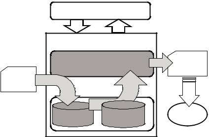
The structure of FTI tool is shown in Figure 1. Fault Tolerance Insertion Procedures work with two libraries, FT-library contains the set of fault tolerant structures and techniques provided together with FTI and WORK-library contains users’ design to be hardened. Throughout a user interface, the user may apply faulttolerance techniques at selected points in the design in a step-by-step fashion.
The main input to FTI tool is the original design, which is described at RT level with a hardware description language. Although FTI tool works with RTL design descriptions, it performs an elaboration for synthesis of the original design description in order to identify the hardware resources. Therefore, hardening process is always hardware-oriented.
The output produced by FTI is the hardened version of the input design, also described at RT level with an HDL. There are two main advantages of maintaining this format. First, it is possible to apply the same tests for functional validation for the original and the hardened versions of the circuit. Second, fault tolerance is evaluated in a high level of abstraction. Finally, once the hardened version of the circuit is validated, it can be processed in the next steps of a typical design flow.
User interface |
|
|
FT insertion tool |
|
|
Fault Tolerance Insertion Procedures |
VHDL |
|
VHDL |
|
output file |
|
|
|
input file |
|
|
WORK |
FT |
To other |
tools |
||
|
Library |
|
Figure 1. FTI Tool Schema.
In order to help designers in the task of hardening, the graphical user interface guides users through different steps, Figure 2. At each step a design modification is performed, users must specify the elements to be hardened and the technique to be applied. The descriptions of components needed for the various fault-tolerance techniques to be applied are available in the component library named FT-library. This FT-library is provided with the tool and could also be enhanced with user’s FT components. Examples of these components are encoders, decoders, checkers, majority voters, comparators, etc. Self-checking designs of particular modules (e.g., typical data path components) can be included as well. These components are inserted

186 |
C. Ló pez-Ongil et al. |
in the design as required for the fault-tolerance techniques to be applied. FTI tool is intended to deal with hierarchical designs, where only critical parts are modified and, finally a complete description of the design is generated.
Figure 2. FTI Tool Graphical User Interface.
FTI tool works with a design representation based on a database format. Modifications and analyses are performed on this database, AIRE CE, which is a standard format for processing designs described with hardware description languages. While in most synthesis environments, intermediate results are stored in internal design databases and cannot be downloaded in standard formats, in FTI tool it is possible to revert the modifications to a HDL code. Therefore, it is possible to download a modified HDL version of the fault-tolerant design. This option provides several advantages:
•It allows performing behavioral simulation of the modified design, in order to validate the correct behavior of the design after the modifications performed. This saves simulation time, because behavioral simulation is far more efficient than gate level simulation
•The user can recognize the modifications performed in the code, providing higher user confidence in the modification process. Manual modifications are still possible, if needed. During the user learning steps, the user may compare the results obtained with the automatic and manual modification process.
•The proposed approach makes automatic insertion of fault-tolerant structures compatible with any design environment supporting an HDL input. Considering that one of the main reasons for the lack of CAD tools in the area of on-line testing has been the relatively small number of users, this is an interesting advantage as it can reach the entire design community independently of the particular design environment used.

Automatic Tools for Design Hardening |
187 |
The proposed approach allows making full use of the synthesis capabilities provided by commercial tools. Components that have been designed manually according to specific techniques can be incorporated in FT-library and inserted under the general insertion mechanisms of the tool.
The Fault-Tolerance Insertion tool (FTI) has been developed using the source code analyzer Tauri [8] and the AIRE CE format [9]. This tool provides an open analysis and elaboration database for VHDL and Verilog designs according to the standards IEEE 1076 and IEEE 1364, respectively. In the sequel, we will use VHDL for the examples. However, note that the proposed techniques can be easily extended to Verilog.
3. Automatic insertion of hardware redundancy
Hardware redundancy is the addition of extra hardware for the purpose of either detecting or tolerating faults. Hardware redundancy techniques achieve fault tolerance by replicating hardware components of the circuit. The outputs of the replicated components are then resolved to produce a single output, which may be coded to cover for possible faults in the output resolution logic. The type and characteristics of the resolution function depends on the particular hardware redundancy technique used.1 For instance, the resolution function for N-Modular Redundancy (NMR) implements a majority voter, while for Duplication With Comparison (DWC) the resolution function implements a comparator of the two replicas and assigns one of the two replicas to the output.
Passive hardware redundancy techniques provide error-free outputs, as they are able to mask the occurrence of faults. In the FTI tool, passive technique available is n- modular redundancy (NMR).
Active hardware redundancy techniques do not provide error-free outputs, but provide an error signal, which is activated in case an error is detected. Error recovery actions are then driven by this signal. In FTI tool, active techniques available are duplication with comparison (DWC) and standby sparing. It is also possible to apply a hybrid technique which mask errors in the outputs and provides an error signal: n- modular redundancy with spares.
With respect to the testability of modified circuit, it must be taken into account that redundancy will worsen testability, but active techniques are generating an error signal that could help in the test of the circuit.
From the previous definitions, any transformation based on a hardware redundancy technique is determined by three main aspects:
•The replication target, which is defined as the piece of hardware that is to be replicated
•The particular hardware redundancy technique to be applied, which mainly defines the output resolution function
•The error recovery actions which are required to recover from a detected error
1This resolution function must not be confounded with HDL resolution functions that solve wired logic
188 |
C. Ló pez-Ongil et al. |
The first two aspects will be described in the following sections. The error recovery actions are common to information redundancy techniques and will be described in section 6, after the insertion of information redundancy.
3.1 Target selection and replication
The target can be specified in terms of VHDL objects (signals, variables and ports) and statements. The associated hardware is then identified and modified in the elaborated model, which provides a RT-level view of the design.
In this model, the target may be a set of objects along with a selected portion of its input cone. Identifying the input cone of a signal can be easily performed in the elaborated model by tracing back the signal up to the primary inputs. A typical case in RTL consists in selecting the input cone of the signal up to the preceding registered signals. This case can be recursively extended to larger portions of the input cone.
Replication of the target consists in identifying the target, by marking the nodes in the selected portion of the input cone of the signal, and inserting copies of the marked nodes (the replicas) in the elaborated model, along with the new object declarations associated to the replicated nodes.
The VHDL code corresponding to the replicas is then generated by tracing back to the analyzed model. This code needs to be modified in order to cover some hardware structures that are not described explicitly in VHDL, such as default assignments to registers. In this case, auxiliary variables are inserted to model explicitly the required behavior.
3.2 Resolution function
The output resolution function must be inserted in order to obtain a single, faulttolerant output from the outputs of the replicated components. For active hardware techniques, such as Duplication With Comparison (DWC), the resolution function also provides an error signal, which is activated in case of error.
The resolution function is inserted by means of a call to a VHDL function or procedure included in the FT-library that corresponds to the required fault-tolerant technique applied.
3.3 Example
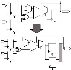
We will illustrate the replication approach by showing the result of applying it to one example. The initial example is shown in Code 1.
Figure 3 shows the hardware inferred from this code (elaborated model) and the result after duplicating the register modeled by signal p. The duplicated signals are labeled with the suffix “_FT0” and “_FT1”. A resolution function is applied afterwards to determine the value of the target signal p. In this example, the resolution function corresponds to DWC technique and is modeled by a VHDL procedure that outputs the value of p and an error signal. The resulting VHDL code is shown in Code 2. Modifications introduced automatically by the FTI tool are shown in bold.
Automatic Tools for Design Hardening |
189 |
Code 1: VHDL description of Example_1
architecture initial of example_1 is
...
begin
...
P1: process(clk, reset) begin
if reset = ‘0’ then data1 <= “000”; data2 <= “000”;
elsif rising_edge(clk) then data1 <= a;
data2 <= b; end if;
end process;
d <= data1 or data2;
P2: process(clk, reset) begin
if reset = ‘0’ then p <= “000”;
elsif rising_edge(clk) then if enable = ‘1’ then
if load = ‘1’ then p <= d;
else
p <= p+’1’; end if;
end if; end if;
end process;
...
end initial;
a
‘1’
b
+ |
P(2:0) |
|
enable |
|
load |
a |
+ |
‘1’ |
|
|
enable |
b |
load |
p_FT0
p_FT1

 Dwc_resol_function
P(2:0)
Figure 3. Elaborated model for the initial and modified example_1.
190 |
C. Ló pez-Ongil et al. |
Note that the feedback input to the register is implicitly defined in VHDL. Just a replication of the statements where signal p is assigned would produce a replication of the feedback loop as well. The solution to replicate exactly the register consists in using an intermediate variable (paux) that models the input to the register and then assigning the replicas to the intermediate variable.
Code 2. Example_1 after duplicating register p
-- Result after duplicating register p architecture code2 of example_1 is
...
begin
...
P1: process(clk, reset) begin
if reset = ‘0’ then data1 <= “000”; data2 <= “000”;
elsif rising_edge(clk) then data1 <= a;
data2 <= b; end if;
end process;
d <= data1 or data2;
P2: process(clk, reset)
-- create auxiliary variable
variable paux:std_logic_vector(2 downto 0);
begin
if reset = ‘0’ then p_FT0 <= “000”; p_FT1 <= “000”;
elsif rising_edge(clk) then
-- assign default value to paux paux := p;
if enable = ‘1’ then if load = ‘1’ then
paux := d; -- paux substitutes p else
paux := p +’1’; end if;
end if;
p_FT0 <= paux; p_FT1 <= paux;
end if; end process;
DWC_resol_function(p_FT0, p_FT1, p, error);
...
end code2;

Automatic Tools for Design Hardening |
191 |
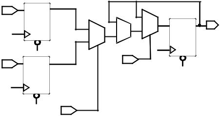
Figure 4 shows the result of duplicating signal p along with its input cone up to the preceding registered signals (data1, data2). The code generated in this case is shown in Code 3
a |
|
|
|
|
‘1’ |
+ |
|
|
|
|
|
|
|
|
||||
|
|
|
|
|
|
|
|
|
|
|||||||||
|
|
|
|
|
|
|
|
|
|
|
|
|
|
|
||||
|
|
|
|
|
|
|
|
|
|
|
|
|
|
|
|
|||
|
|
|
|
|
|
|
|
|
|
|
|
|
|
|
|
|||
|
|
|
|
|
|
|
|
|
|
|
|
|
|
|
|
|
|
|
|
|
|
|
|
|
|
|
|
|
|
|
|
|
|
|
|
|
|
|
|
|
|
|
|
|
|
|
|
|
|
|
|
|
|
|
|
|
|
|
|
|
|
|
|
|
|
|
|
|
|
|
|
|
|
|
|
|
|
|
|
|
|
|
|
|
|
|
|
|
|
|
|
|
|
|
b |
|
|
|
|
|
|
|
enable |
|
|
|
|
|
|
|
|
|
|
|
|
|
|
|
|
|
load |
|||
|
|
|
|
|
|
||||
|
|
|
|
|
|
|
|||
a |
|
|
|
|
|
|
|
|
|
|
+ |
|
|
|
|
|
|
|
|
|
|
|
|
|
|
|
|
|
|
|
|
|
|
|
|
|
|
|
|
|
|
|
|
|
|
|
|
|
|||
|
|
|
|
|
|
|
|
|
|
|
|
|
|
|
|
|
|
|
|
|
|
|
|||
|
|
|
|
|
|
|
|
|
|
|
|
|
|
|
|
|
|
|
|
|
|||||
|
|
|
|
|
|
|
|
‘1’ |
|
|
|
|
|
|
|
|
|
|
|
|
|
||||
|
|
|
|
|
|
|
|
|
|
|
|
|
|
|
|
|
|
|
|
|
|
|
|
|
|
|
|
|
|
|
|
|
|
|
|
|
|
|
|
|
|
|
|
|
|
|
|
|
|
|
|
|
|
|
|
|
|
|
|
|
|
|
|
|
|
|
|
|
|
|
|
|
|
|
|
|
|
|
|
|
|
|
|
|
|
|
|
|
|
|
|
|
|
|
|
|
|
|
|
|
|
|
|
|
|
|
|
|
|
|
|
|
|
|
|
|
|
|
|
|
|
|
|
|
|
|
|
|
|
b |
|
|
|
|
|
|
|
|
|
|
|
|
|
|
|
|
|
|
enable |
|
|
|
|||
|
|
|
|
|
|
|
|
|
|
|
|
|
|
|
|
|
|
|
|
|
|
|
|
|
|
|
|
|
|
|
|
|
|
load |
|
|
|
||||||||||||||
|
|
|
|
|
|
|
|||||||||||||||||||
|
|
|
|
|
|
|
|
|
|
|
|
|
|
|
|
|
|
|
|
|
|
|
|
|
|
|
|
|
|
|
|
|
|
|
|
|
|
|
|
|
|
|
|
|
|
|
|
|
|
|
|
|
|
|
|
|
|
|
|
|
|
|
|
|
|
|
|
|
|
|
|
|
|
|
|
|
|
|
|
|
|
|
|
|
|
|
|
|
|
|
|
|
|
|
|
|
|
|
|
|
|
|
|
|
|
|
|
|
|
|
|
|
|
|
|
|
|
|
|
|
|
|
|
|
|
|
|
|
|
 DWC_resol_function
P(2:0)
Figure 4. Elaborated model after replicating p and its input cone.
Code 3. Example after replicating p and its input cone
--Result after duplicating register p
--along with its input cone architecture code3 of example is
...
begin
...
process(clk, reset) begin
if reset = ‘0’ then data1 <= “000”; data2 <= “000”;
elsif rising_edge(clk) then data1 <= a;
data2 <= b; end if;
end process;
data1_FT0 <= data1; data1_FT1 <= data1; data2_FT0 <= data2; data2_FT1 <= data2;
enable_FT0 <= enable; enable_FT1 <= enable; load_FT0 <= load; load_FT1 <= load;
192 |
C. Ló pez-Ongil et al. |
d_FT0 <= data1_FT0 or data2_FT0; d_FT1 <= data1_FT1 or data2_FT1;
process(clk, reset) begin
if reset = ‘0’ then p_FT0 <= “000”;
elsif rising_edge(clk) then if enable_FT0 = ‘1’ then if load_FT0 = ‘1’ then
p_FT0 <= d_FT0; else
p_FT0 <= p_FT0 +’1’; end if;
end if; end if;
end process;
process(clk, reset) begin
if reset = ‘0’ then p_FT1 <= “000”;
elsif rising_edge(clk) then if enable_FT1 = ‘1’ then if load_FT1 = ‘1’ then
p_FT1 <= d_FT1; else
p_FT1 <= p_FT1 +’1’; end if;
end if; end if;
end process;
DWC_resol_function(p_FT0, p_FT1, p, error);
...
end code3;
4. Automatic insertion of information redundancy
Information redundancy techniques achieve fault-tolerance by using redundant codes for data. The result of adding information redundancy is that a portion of dataflow works with encoded data. Therefore, a set of operations must be provided in order to encode data at the beginning of the selected portion of dataflow, to decode data at the end of the selected portion of data flow, as well as to modify buses and operators for the required data code.
The encoding of a portion of dataflow can be obtained through a composition of the following basic operations:
Automatic Tools for Design Hardening |
193 |
•Insert an encoder at a selected point
•Insert a decoder/checker at a selected point
•Substitute an existing operator by the equivalent operator that operates on coded data
•Extend the size of selected data to accommodate the extra bits required by the redundant code used
The insertion of an encoder has the effect of generating a new signal (the encoded signal), which will substitute the original unencoded signal for all or some of its fanouts. Analogously, the insertion of a decoder has the effect of generating a new signal (the decoded signal), which will substitute the original encoded signal for all or some of its fan-outs. The insertion of a checker has the effect of generating a new signal (the error signal), which will be further used to drive some error recovery actions. Note that for non-separable codes, decoding and checking operations are usually performed jointly by a decoder/checker in order to save hardware.
The insertion of a encoder, decoder or checker is implemented by inserting a new object declaration (the encoded, decoded or error signal, depending on the case) with the appropriate size, inserting the appropriate function (encoder, decoder or checker function) in between the target signal and the new signal, and substitute the target signal with the new signal for all or some of the fan-outs of the target signal.
Operator substitution consists in substituting the operator by another operator available in the FT-library. Extending the data size consists in extending the range of the declaration of the target object with the extra bits required for the particular code used.
By properly using these operations, a portion of dataflow can be made to work with a redundant code. In addition, a checker can be used in order to verify the coherence of the data after the application of these operations in order to detect possible mistakes. Such a checker validates the following properties:
•The type and range of any object must be consistent with the values assigned to the object. This property is checked during analysis in the original circuit and is part of the analyzer. The check is now extended to the modified portions of the design.
•Signals that convey encoded (unencoded) data should not be assigned to signals that convey unencoded (encoded) data, except through the appropriate element (decoder or encoder). This can be verified in the elaborated model by marking the portion of the circuit that uses encoded data.
In the proposed tool, error detecting codes available are parity codes and unordered codes (Berger and 2-out-of-n codes). Also, error correcting codes are provided, such as Hamming error codes.
4.1 Examples
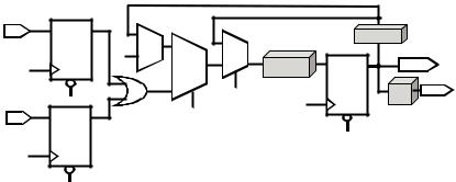
Consider again the example shown in Code 1. Figure 5 shows the hardware modified after encoding just the register modeled by signal p. The code produced after the modification is shown in Code 4 (only for process P2). The encode, decode and check functions are general and can be bound to the appropriate functions in the FT-library for the particular code used. In the case of a non-separable code, the decode and check
194 |
C. Ló pez-Ongil et al. |
function calls will be substituted by a single procedure call to the corresponding decoder/checker.
Note that the auxiliary variable paux is again used in order to model explicitly the feedback to the register.
a
‘1’
b
+ |
|
decoder |
|
encoder |
P(2:0) |
||
|
enable |
check |
Error |
|
load |
|
|
Figure 5. Elaborated model after encoding register p.
Code 4 Example_1 after encoding register p
architecture code4 of example
signal p: std_logic_vector(extended_size); signal dec_p: std_logic_vector(2 downto 0);
begin
...
P2: process(clk, reset)
variable paux:std_logic_vector(2 downto 0);
begin
if reset = ‘0’ then p <= “000”;
elsif rising_edge(clk) then paux := dec_p;
if enable = ‘1’ then if load = ‘1’ then
paux := d; else
paux := paux +’1’; end if;
end if;
p <= encode(paux); end if;
end process;
error <= check(p); decoded_p <= decode(p)
end code4;
Bla, bla, bla
Automatic Tools for Design Hardening |
195 |
Code 5. VHDL description of Example_2: ACCUM
library IEEE; |
|
|
||
use |
IEEE.std_logic_1164.all; |
|||
use |
IEEE.std_logic_unsigned.all; |
|||
entity ACCUM is |
|
|
||
port( |
|
|
|
|
|
signal |
Clk |
: in |
std_logic; |
|
signal |
Reset |
: in |
std_logic; |
|
signal |
En |
: in |
std_logic; |
|
signal |
Sel |
: in |
std_logic; |
|
signal |
AD |
: in |
std_logic_vector(7 downto 0); |
|
signal |
BD |
: in |
std_logic_vector(7 downto 0); |
|
signal |
S |
: out std_logic_vector(7 downto 0)); |
|
end |
ACCUM; |
|
|
|
architecture A_ACCUM of ACCUM is |
||||
|
signal |
A |
: std_logic; |
|
|
signal |
B |
: std_logic; |
|
|
signal |
D |
: std_logic; |
|
|
signal |
Q |
: std_logic; |
|
begin |
|
|
|
|
REG_A: process(Clk, Reset) |
||||
begin |
|
|
|
|
|
if Reset = ‘0’ |
then |
|
|
|
A <= |
(others |
=> ‘0’); |
|
|
elsif Clk’event and Clk = ‘1’ then |
|||
|
if En = ‘1’ then |
|
||
|
A <= AD; |
|
|
|
|
end if; |
|
|
|
|
end if; |
|
|
|
end process REG_A; |
|
|||
REG_R: process(Clk, Reset) |
||||
begin |
|
|
|
|
|
if Reset = ‘0’ |
then |
|
|
|
B <= |
(others |
=> ‘0’); |
|
|
elsif Clk’event and Clk = ‘1’ then |
|||
|
if En = ‘1’ then |
|
||
|
B <= BD; |
|
|
|
|
end if; |
|
|
|
|
end if; |
|
|
|
end process REG_B; |
|
|||
D |
<= A when Sel = ‘1’ else B; |
|||
ACCUM_P: process(Clk, Reset) |
||||
begin |
|
|
|
|
|
if Reset = ‘0’ |
then |
|
|
|
Q <= |
(others |
=> ‘0’); |
|
elsif Clk’event and Clk = ‘1’ then if En = ‘1’ then
196 |
|
|
|
C. Ló pez-Ongil et al. |
|
Q <= Q + D; |
|
|
|
|
end if; |
|
|
|
|
end if; |
|
|
|
end process ACCUM_P; |
|
|
|
|
end A_ACCUM; |
|
|
|
|
|
|
|
Q |
|
AD |
A |
|
|
|
|
|
+ |
|
|
|
|
|
S |
|
|
|
|
|
|
|
|
D |
|
|
BD |
B |
|
En |
|
|
|
|
|
|
Sel
Figure 6. Elaborated model of ACCUM example.
Code 6. Example_2: ACCUM after parity encoding of the whole block and decoding output S
library IEEE;
use IEEE.std_logic_1164.all;
use IEEE.std_logic_unsigned.all; use WORK.parity.all;
use WORK.fti_attr.all;
entity ACCUM |
is |
|
|
port( |
|
|
|
signal Clk |
: in |
std_logic; |
|
signal Reset |
: in |
std_logic; |
|
signal En |
|
: in |
std_logic; |
signal Sel |
: in |
std_logic; |
|
signal AD |
|
: in |
std_logic_vector(7 downto 0); |
signal BD |
|
: in |
std_logic_vector(7 downto 0); |
signal S |
|
: out |
std_logic_vector(7 downto 0)); |
end ACCUM; |
|
|
|
architecture |
Code_6 of ACCUM is |
||
signal A |
|
: std_logic; |
|
signal B |
|
: std_logic; |
|
Automatic Tools for Design Hardening |
197 |
signal D |
: |
std_logic; |
|
signal Q |
: |
std_logic; |
|
attribute fti of |
A : signal is |
“parity”; |
|
attribute fti of |
B : signal is |
“parity”; |
|
attribute fti of |
D : signal is |
“parity”; |
|
attribute fti of |
Q : signal is |
“parity”; |
|
signal AD_FT |
: |
std_logic_vector(7 downto 0); |
|
attribute fti of |
AD_FT : signal is “parity”; |
||
signal BD_FT |
: |
std_logic_vector(7 downto 0); |
|
attribute fti of |
BD_FT : signal is “parity”; |
||
signal s_FT |
: |
std_logic_vector(7 downto 0); |
|
attribute fti of |
S_FT : signal |
is “parity”; |
|
signal EOUT |
|
: std_logic; |
|
attribute fti of |
EOUT : signal |
is “ERROR_SIGNAL”; |
|
begin |
|
|
|
REG_A: process(Clk, Reset) begin
if Reset = ‘0’ then
A <= (others => ‘0’);
elsif Clk’event and Clk = ‘1’ then if En = ‘1’ then
A <= AD_FT; end if;
end if;
end process REG_A;
REG_B: process(Clk, Reset) begin
if Reset = ‘0’ then
B <= (others => ‘0’);
elsif Clk’event and Clk = ‘1’ then if En = ‘1’ then
B <= BD_FT; end if;
end if;
end process REG_B;
MUX : D <= A when Sel = ‘1’ else B;
ACCUM_P: process(Clk, Reset) begin
if Reset = ‘0’ then
Q <= (others => ‘0’);
elsif Clk’event and Clk = ‘1’ then if En = ‘1’ then
Q <= WORK.parity.add(a => Q, b => D); end if;
end if;
end process ACCUM_P;
S_FT <= Q;
AD_FT <= WORK.parity.encoder(bus_in => AD); BD_FT <= WORK.parity.encoder(bus_in => BD);
198 |
|
|
|
C. Ló pez-Ongil et al. |
S |
<= |
WORK.parity.decoder(bus_in |
=> |
s_FT); |
EOUT |
<= |
WORK.parity.checker(bus_in |
=> |
s_FT); |
end Code_6;
AD |
encode |
A |
|
||
BD |
encode |
B |
|
Sel
|
Q |
|
|
D |
+ |
decode |
S |
|
|
||
|
En |
|
|
|
|
check |
EOUT |
|
|
|
Figure 7. Elaborated model of Code 6, all block works with parity and parity checking is performed at the output S.
In the case of a Finite State Machine (FSM), the states are usually described in VHDL by means of a user-defined enumerated type. State coding is then performed automatically by the synthesis tool using a default code or a user-specified code. Rather than explicitly inserting an encoder and a decoder, the state coding can be easily changed to a redundant code in this case by setting a code to be used by the synthesis tool.
The VHDL Register Transfer Level Synthesis Standard IEEE 1076.6 [10] specifies the attribute ENUM_ENCODING that shall be supported for synthesis. The attribute ENUM_ENCODING provides the means to specify the encoding of enumeration type values. Redundant codes for enumerated types will be introduced by inserting a specification of the ENUM_ENCODING attribute.
5. Error recovery actions
Error recovery actions define the hardware to be inserted in order to process the error signals generated by techniques that do not have fault masking capabilities.
In a general case, the automatization of error recovery actions may be very difficult to implement because it requires specific knowledge of the functionality of the circuit. However, in most practical cases error recovery actions fall in one of the following categories:
•Disabling the load of a register
•Disabling the setting of a control signal (e.g., global reset)
•Controlling the multiplexing of spare units
Automatic Tools for Design Hardening |
199 |
These cases can be easily supported in an automatic way. The following example shows how a register model can be modified so that it is disabled in case an error occurs. A dual-rail register output can be produced (not shown in the example) by applying a hardware redundancy technique as described in section 3, if required.
Code 5. VHDL initial description of example_3: Register
process(clk, reset) begin
if reset = ‘0’ then q <= ‘0’;
elsif rising_edge(clk) then if enable = ‘1’ then
q <= d; end if;
end if; end process;
Code 6. VHDL description of Example_3 with error disabling
process(clk, reset) begin
if reset = ‘0’ then q <= ‘0’;
elsif rising_edge(clk) then if error = “01” then
if enable = ‘1’ then q <= d;
end if; end if;
end if; end process;
6. Conclusions
In this work we present FTI tool, which automates the insertion of fault-tolerant structures in design descriptions at RT level. Techniques to automatically apply hardware redundancy and information redundancy to a design have been shown. The resulting fault-tolerant design is also obtained in the form of a RT level design description that can be further simulated and synthesized with commercial tools.
Proposed solution will imply higher design productivity thanks to the automation of hardening process. As well, reliability of circuits is enhanced due to the elimination of manual design mistakes and the possibility of early fault tolerance validation.
Developed tool has been validated with some benchmarks. Those are academic and industrial designs. First one is a PIC micro-controller and second is an aero-spatial FPGA (Rosetta SADE) developed by UC3M for Alcatel-Espacio. Obtained results are
200 |
C. Ló pez-Ongil et al. |
satisfactory, CPU time and memory used during application is negligible while VHDL descriptions obtained are 100% correct.
The proposed tool provides an automatic way to substitute current manual practices in the design of fault-tolerant circuits.
References
[1]“Minimizing Single Event Upset Using Synopsys”. Application Note, Actel Corporation, July 1998.
[2]XTMR Tool. “http://www.xilinx.com/products/milaero/tmr/index.htm”
[3]R. O. Duarte, M. Nicolaidis, H. Bederr, Y. Zorian. “Efficient Fault-Secure Shifter Design”. Journal of Electronic Testing, Theory and Applications (JETTA), vol. 12, p. 2939, 1998
[4]M. Nicolaidis, R. O. Duarte, S. Manich, J. Figueras. “Achieving Fault Secureness in Parity Prediction Arithmetic Operators”. IEEE Design and Test of Computers, April-June 1997.
[5]R. O Duarte, I. A. Noufal, M. Nicolaidis. “A CAD Framework for Efficient Self-Checking Data Path Design”. IEEE International On-Line Testing Workshop, July 1997
[6]M. Nicolaidis, Y. Zorian. “On-Line Testing for VLSI- A Compendium of Approaches”. Journal of Electronic Testing, Theory and Applications (JETTA), vol. 12, p. 7-20, 1998
[7]L.Berrojo, F.Corno, L.Entrena, I.González, C. López-Ongil, M.Sonza-Reorda, G.Squillero. “An Industrial Environment for High-Level Fault-Tolerant Structures Insertion and Validation”. Proceeding of the 20th IEEE VLSI Test Symposium. 2002.
[8]TauriTM. FTL Systems Inc.
[9]AIRE CE “Advanced Intermediate Representation with Extensibility/Common Environment ”John Willis, Technical Editor / Architect (FTL Systems, Inc.). Version. 7 Pre-Release (2000).
[10]“IEEE P1076.6/D1.12 Draft Standard For VHDL Register Transfer Level Synthesis”. IEEE, 1998.