


page 274
46.2 INJECTION MOLDING
•Basic process - Heat a thermoplastic material until it melts. Force it into a hollow (cooled) cavity under pressure to fill the mold. When cool remove the finished part.
•Typical materials are,
-nylon
-styrene
-ethylene
•A typical injection moulding machine is seen below with the covers removed. Plastic pellets are poured in the hopper, and finished parts emerge from the dies.
|
screw |
plattens |
|
hopper |
heater bands |
mold |
|
|
|
||
|
|
halves |
mold clamp |
|
|
|
|
screw |
|
|
|
motor |
|
|
|
|
frame |
|
|
•Injection system,
-a material hopper acts as an input buffer
-a heated chamber melts the material
-an injector forces the now viscous fluid into the mold
•Previous mechanisms used an injection plunger.
•Current mechanisms use a reciprocating screw,
-basically the screw extends from the hopper to the injection chamber.
-along the length of the screw chamber, heater bands are used to melt the plastic.
-as the screw turns, it moves raw solid plastic from the hopper, to the injection chamber. The buildup of pressure in the injection chamber forces the screw back until enough for a shot has accumulated.
-the screw is forced forward to inject the plastic into the mold.
page 275
Raw Plastic Pellets poured into hopper
|
|
|
|
|
|
|
|
|
|
|
|
|
|
|
|
|
|
|
|
|
|
|
|
|
|
|
|
|
|
|
|
|
|
|
|
|
|
|
|
|
|
|
|
|
|
|
|
|
|
|
|
|
|
|
|
|
|
|
|
|
|
|
|
|
|
|
|
|
|
|
|
|
|
|
|
|
|
|
|
|
|
|
|
|
|
|
|
|
|
|
|
|
|
|
|
|
|
|
|
|
|
|
|
|
|
|
|
|
|
|
|
|
|
|
|
|
|
|
|
|
|
|
|
|
|
|
|
|
|
|
|
|
|
|
|
|
|
|
|
|
|
|
|
|
|
|
|
|
|
|
|
|
|
|
|
|
|
|
|
|
|
|
|
|
|
|
|
|
|
|
|
|
|
|
|
|
|
|
|
|
|
|
|
|
|
|
|
|
|
|
|
|
|
|
|
|
|
|
|
|
|
|
|
|
|
|
|
|
|
|
|
|
|
|
|
|
|
|
|
|
|
|
|
|
|
|
|
|
|
|
|
|
|
|
|
|
|
|
|
|
|
|
|
|
|
|
|
|
|
|
|
|
|
|
|
|
|
|
|
|
|
|
|
|
|
|
|
|
|
|
|
|
|
|
|
|
|
|
|
|
|
|
|
|
|
|
|
Molten plastic |
|
|
Heater bands supply heat to the barrel |
|
|
|
|
||||||||||||||||
emerges when the |
|
|
|
|
|
|
|
|
|
|
|
|
|
|
|
|
|
|
|||||
screw is advanced |
|
|
|
|
|
|
|
|
|
|
|
|
|
|
|
|
|
|
|||||
|
|
|
|
|
|
|
|
|
screw |
|
|
screw |
|
screw |
|||
metering |
|
|
compression |
|
feed |
|||
|
|
|||||||
zone |
|
|
zone |
zone |
||||
-there is a contribution to melting by pressure that allows the temperature of the heating bands to be lower.
-the purpose of the screw is to generate a homogenous melt with little orientation in flow direction.
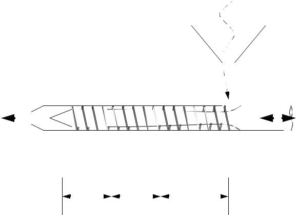
•Typical zones can be identified on the screw,
-feed - a screw with large cavities to carry more material.
-compression - the depths of the screw thread reduce, leading to elevated pressures, and pressure induced melting.
-metering - small and uniform threads to provide controlled quantities. This also serves as a final mixing stage.
•Screws are often low/medium/high compression ratio as a result of the change of screw volume from the feed to the metering stages - screw selection will vary between materials, but a low compression ration screw will ensure good melting in most cases.
•Screws are nitride treated to improve tool life. Screws might also be made slightly smaller to compensate for thermal expansion when heated.
•Screws are often driven by electric or hydraulic motors.
page 276
•The heat capacity and melting point temperatures of various materials determine the energy required to melt the plastic and the energy to be removed for solidification (and for ejection).
•The volume of the injection chamber determines the maximum mold cavity size. The volume provided is often for polystyrene. When using other materials the volume can be corrected using the following formula. For example a 10 oz. shot,
SGmaterial |
( ozshot) |
= |
|
SGmaterial |
( ozshot) |
|
SG------------------------------ |
|
|
------------------------1.05 |
|||
|
polystyrene |
|
|
|
|
|
•The mold is held closed with a certain clamp tonnage.
•As cycle times decrease, the plastic melt becomes less consistent.
•Each heating zone uses electrical heating bands with thermocouples, or pyrometers to control the temperature.
•When injecting, the mold is moved then clamped shut. The mold halves are mounted/clamped/ screwed on two platens, one fixed, one moving. The stationary platen has a locating ring to allow positioning on the mold half over the injection nozzle. The moving half has ejector pins to knock out the finished part. Larger plates are found on larger injection molding machines.
•Injection molding machines pressure is calculated as injection pressure over an area in the mold. Consider the case where a mold with a 10 square inch mold is being filled in a 200 ton machine.
|
F |
|
200 |
|
tons |
|
|
P = |
A-- |
= |
--------10 |
= 20 |
inch------------- |
2 |
= 40ksi |
|
|
|
|
|
|
|
|
• The platens are actuated by hydraulic driven mechanisms. These are slow, but can exert great forces. In lighter presses other mechanisms can be used.

page 277
A single toggle clamped mechanism shown in the locked position
A double toggle clamp in the locked position