

page 179
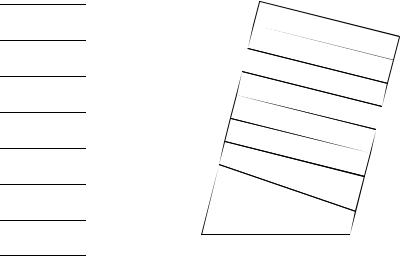
For the angle 12°37’13”, find the angular gauge block stack using the 16 piece set.
12°37’13” -3”
12°37’10”
+30”
12°37’40”
+20”
12°38’ -30’
12°8’ -5’
12°3’ -3’
12°
+3°
15° -15°
0
|
|
- |
|
|
|
|
|
|
|
3” |
|
|
|
|
|
|
|
+3 |
0 |
|
|
- |
|
|
+ |
|
” |
|
3 |
0 |
2 |
|
||
|
-5’ |
|
’ |
|
0” |
|
|
|
|
|
|
|
|
|
- |
|
|
|
|
|
|
3’ |
|
|
|
|
|
|
|
|
|
+ |
|
|
- |
|
|
|
3° |
|
|
1 |
5 |
|
|
|
|
|
|
° |
|
|
|
|
|
35.6.5 Practice Problems
1.From the same set of gauge blocks build up the dimensions 3.2452” and 3.2462”. You must not use the same gauge blocks twice. Use the 83 piece gauge block set.
35.6.6 Limit (GO & NO GO) Gauges
•These gauges are made for simple pass/fail inspection
•Basically there are two separate, or combined gauges for each feature to be measured.
•One gauge must fit inside the feature, and the second must not. In other words the GO gauge must fit inside/outside the feature, the NO GO gauge must not. If the GO gauge does not fit, the tolerance is above the maximum metal tolerance. If the NO GO gauge goes, the feature is
below the minimum metal tolerance.
page 180
•This method is best suited to unskilled operators testing many parts, although more modern quality methods suggest this procedure should be replaced with Statistical Process Control (SPC).
•This method can also be used for inspection rooms, and limited runs using gauge blocks.
35.6.6.1 - Basic Concepts
•The GO gauge is made near the maximum metal condition. The GO gauge must be able to slip inside/over the feature without obstruction.
•The NO GO gauge is made near the minimum metal condition. The NO GO gauge must not be able to slip inside/over the feature.
•The terms minimum metal condition, and maximum metal condition are used to describe the tolerance state of a workpiece. If we assume (at least for now) that all parts are made by removing metal from larger pieces, then we are trying to remove a certain amount. If we are drilling a hole the maximum metal condition will be when the hole is small, and extra metal is ‘left behind’. The minimum metal condition would be when the hole has been overdrilled and as little metal as possible is left behind. The tolerances often set the acceptable maximum and minimum metal conditions. If features are external, the maximum metal condition is their largest size, and minimum metal condition is their smallest size.
page 181
Maximum Material Hole |
|
Minimum Material Bottom |
0.5” |
As Specified
1”±0.5”
2.75”
Minimum Material Hole
Maximum Material Bottom
1.5”
3”±0.25”
3.25”
•A basic set of shapes these typically deal with are,
-plug
-ring
-taper
-snap
-threads
•These are good for work tolerances down to about 0.002” (anything less should use comparators)
35.6.6.2 - GO & NO GO Gauges Using Gauge Blocks
•Simple GO & NO GO gauges for internal features can be made from gauge blocks.
•The basic procedure is,
1.Determine the dimension and tolerance of the feature to be tested.
2.Check the temperature of the measurement environment.
3.Determine the upper/lower dimensional limits
page 182
4.If the gauge blocks are not being used at the rated temperature, adjust the dimensions.
5.Determine the gauge block stacks for both the GO and NO GO gauges.
6.Test.
+.003” 5.000” -.001”
Given:
If the Part is aluminum the coefficient of linear thermal expansion is C = 0.0000127°F in./in.
Assume the coefficient for the gauge blocks is C = 0.0000061°F in./in. The temperature in the measurement room is 76°F.
The rated temperature for the gauge blocks is 64°F.
The maximum metal dimension is 5.000-0.001 = 4.999” for the GO gauge. The minimum metal dimension is 5.000+0.003 = 5.003” for the NOGO gauge.
Find the needed change in the gauge block size as a result of the temperature difference.
∆ L = ( ∆ T) (∆ C) ( L)
∆ L = ( 76 – 64) ( 0.0000127 – 0.0000061) ( 5.000in.)∆ L = 0.0005in.
The new size for the GO gauge is 4.999”+0.0005” = 4.9995”
The new size for the NO GO gauge is 5.003”+0.0005” = 5.0035”
Make up the gauge block stacks. (Note when two stacks are taken from the same set, some planning will be required not to use the same block twice.)
35.6.6.3 - Taylor’s Theory for Limit Gauge Design
1.GO gauges should check all features for maximum metal condition at one time
2.NO GO gauges should check only one feature at a time for minimum metal condition
• The example below should illustrate the two points,
page 183
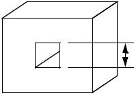
The square hole is to be checked for height and width 
A GO gauge is designed that must fit inside the hole 

If either of the dimensions are too small, the gauge will not GO, and thus the part will fail inspection.
These gauges could be split into two different gauges without any effect on accuracy, but they would require more time for measurement.
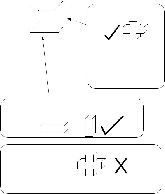
Option A: The correct method with two separate gauges each measuring one of the dimensions. If either of the gauges goes into the hole, then the part will fail inspection.
Option B: This INCORRECT method uses two NO GO gauges joined, this results in a gauge as pictured below. 

It is possible for one of the gauge dimensions to be stuck (passes inspection), while the other dimension is not stuck (fails inspection), but because one of the dimensions is stuck, the gauge does not go, and the part falsely passes inspection.
35.6.6.4 - Gauge Maker’sTolerances
• Because gauges have to be manufactured themselves, they must also have tolerances asigned.
page 184
•The Unilateral System is very popular,
1.A general tolerance is applied to both GO & NO GO gauges of 10% of the work tolerances
2.If work tolerances are above 0.0035”, a wear allowance of 5% of the work tolerance is added to the GO gauge only
3.All gauge tolerances are made to fall within the work tolerance zones. The effect is that the gauges will always be between the maximum tolerance limits, and no bad parts should be accepted. The only downside is that some good parts will also be rejected.
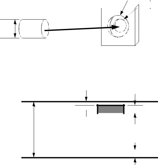
•An example of the Unilateral Tolerance System applied to GO & NO GO gauges is given below, as applied to a shaft (here we are measuring external features). The gauge shown is a gap and ring gauge.
D2±T 2/2 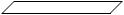
 D3±T 3/2
D1±T 1/2
Shaft (the work)
A GO & NO GO gauge combination (Note: a good part will fit inside the first hole, but not the second)
D1, T1 = The shaft diameter, and tolerance specified by the designer
D2, T2 = The GO gauge diameter and tolerance
D3, T3 = the NO GO gauge diameter and tolerance
GO gauge
D1+T1/2
 10% T1 = T2 5% T1

wear allowance
T1
NO GO gauge
|
|
|
|
|
|
D1-T1/2 |
|
|
|
10% T1 = T3 |
|
|
|
||||
• We can also look at an example of a hole that is to be measured with GO & NO GO gauges (an