- •1. TABLE OF CONTENTS
- •2. BASIC MANUFACTURING
- •2.1 INTRODUCTION
- •2.2 PRACTICE PROBLEMS
- •3. MANUFACTURING COST ESTIMATING
- •3.1 COSTS ESTIMATES
- •3.2 COGS (COST OF GOODS SOLD)
- •3.3 VALUE ENGINEERING
- •3.4 REFERENCES
- •4. BASIC CUTTING TOOLS
- •4.1 CUTTING SPEEDS, FEEDS, TOOLS AND TIMES
- •4.2 HIGH SPEED MACHINING
- •4.3 REFERENCES
- •5. CUTTING THEORY
- •5.1 CHIP FORMATION
- •5.2 THE MECHANISM OF CUTTING
- •5.2.1 Force Calculations
- •5.2.1.1 - Force Calculations
- •5.2.1.2 - Merchant’s Force Circle With Drafting (Optional)
- •5.3 POWER CONSUMED IN CUTTING
- •5.4 PRACTICE QUESTIONS
- •5.5 TEMPERATURES IN CUTTING
- •5.6 TOOL WEAR
- •5.7 CUTTING TOOL MATERIALS
- •5.7.1 A Short List of Tool Materials
- •5.8 TOOL LIFE
- •5.8.1 The Economics of Metal Cutting
- •5.9 REFERENCES
- •5.10 PRACTICE PROBLEMS
- •6. SAWS
- •6.1 SPEEDS AND FEEDS
- •6.2 PRACTICE PROBLEMS
- •7. DRILLING
- •7.1 TYPES OF DRILL PRESSES
- •7.2 TYPICAL DRILL PRESS OPERATIONS
- •7.3 TYPICAL DRILL BITS
- •7.3.1 Reamers
- •7.3.2 Boring
- •7.3.3 Taps
- •7.4 DRILLING PROCESS PARAMETERS
- •7.4.1 The mrr For Drilling
- •7.5 PRACTICE PROBLEMS
- •8. LATHES
- •8.1 INTRODUCTION
- •8.2 OPERATIONS ON A LATHE
- •8.2.1 Machine tools
- •8.2.1.1 - Production Machines
- •8.3 LATHE TOOLBITS
- •8.3.1 Thread Cutting On A Lathe
- •8.3.2 Cutting Tapers
- •8.3.3 Turning Tapers on Lathes
- •8.4 FEEDS AND SPEEDS
- •8.4.1 The mrr for Turning
- •8.4.2 Process Planning for Turning
- •8.5 PRACTICE PROBLEMS
- •9. MILLING
- •9.1 INTRODUCTION
- •9.1.1 Types of Milling Operations
- •9.1.1.1 - Arbor Milling
- •9.1.2 Milling Cutters
- •9.1.3 Milling Cutting Mechanism
- •9.1.3.1 - Up-Cut Milling
- •9.1.3.2 - Down-Cut Milling
- •9.2 FEEDS AND SPEEDS
- •9.2.1 The mrr for Milling
- •9.2.2 Process Planning for Prismatic Parts
- •9.2.3 Indexing
- •9.3 PRACTICE PROBLEMS
- •10. GRINDING
- •10.1 OPERATIONS
- •10.2 MACHINE TYPES
- •10.2.1 Surface
- •10.2.2 Center
- •10.2.3 Centerless
- •10.2.4 Internal
- •10.3 GRINDING WHEELS
- •10.3.1 Operation Parameters
- •10.4 PRACTICE PROBLEMS
- •11. SURFACES
- •11.1 MEASURES OF ROUGHNESS
- •11.2 METHODS OF MEASURING SURFACE ROUGHNESS
- •11.2.1 Observation Methods
- •11.2.2 Stylus Equipment
- •11.2.3 Specifications on Drawings
- •11.3 OTHER SYSTEMS
- •11.4 PRACTICE PROBLEMS
- •11.4.0.1 - Roundness Testing
- •11.4.0.1.1 - Intrinsic Roundness Testing
- •11.4.0.1.2 - Extrinsic Roundness Testing
- •11.4.0.1.3 - Practice Problems
- •11.5 PRACTICE PROBLEMS
- •35. METROLOGY
- •35.1 INTRODUCTION
- •35.1.1 The Role of Metrology
- •35.2 DEFINITIONS
- •35.3 STANDARDS
- •35.3.1 Scales
- •35.3.2 Calipers
- •35.3.3 Transfer Gauges
- •35.4 INSTRUMENTS
- •35.4.1 Vernier Scales
- •35.4.2 Micrometer Scales
- •35.4.2.1 - The Principle of Magnification
- •35.4.2.2 - The Principle of Alignment
- •35.4.3 Dial Indicators
- •35.4.4 The Tool Makers Microscope
- •35.4.5 Metrology Summary
- •35.5 PRACTICE PROBLEMS
- •35.5.0.1 - Interferometry (REWORK)
- •35.5.0.1.1 - Light Waves and Interference
- •35.5.0.1.2 - Optical Flats
- •35.5.0.1.3 - Interpreting Interference Patterns
- •35.5.0.1.4 - Types of Interferometers
- •35.5.0.2 - Laser Measurements of Relative Distance
- •35.5.0.2.1 - Practice Problems
- •35.6 GAUGE BLOCKS
- •35.6.1 Manufacturing Gauge Blocks
- •35.6.2 Compensating for Temperature Variations
- •35.6.2.1 - References
- •35.6.3 Testing For Known Dimensions With Standards
- •35.6.3.1 - References
- •35.6.4 Odd Topics
- •35.6.5 Practice Problems
- •35.6.6 Limit (GO & NO GO) Gauges
- •35.6.6.1 - Basic Concepts
- •35.6.6.2 - GO & NO GO Gauges Using Gauge Blocks
- •35.6.6.3 - Taylor’s Theory for Limit Gauge Design
- •35.6.6.4.1 - Sample Problems
- •35.6.7 Sine Bars
- •35.6.7.1 - Sine Bar Limitations
- •35.6.7.1.1 - Practice Problems
- •35.6.8 Comparators
- •35.6.8.1 - Mechanical Comparators
- •35.6.8.2 - Mechanical and Optical Comparators
- •35.6.8.3 - Optical Comparators
- •35.6.8.4 - Pneumatic Comparators
- •35.6.9 Autocollimators
- •35.6.10 Level Gauges
- •35.6.10.1 - Clinometer
- •35.6.10.2 - The Brookes Level Comparator
- •35.6.11 The Angle Dekkor
- •35.7 MEASURING APARATUS
- •35.7.1 Reference Planes
- •35.7.1.1 - Granite Surface Plates
- •35.7.1.2 - Cast Iron Surface Plates
- •35.7.2 Squares
- •35.7.2.1 - Coordinate Measureing Machines
- •35.7.2.2 - Practice Problems
- •AM:35.7.3 Coordinate Measuring Machines (CMM)
- •36. ASSEMBLY
- •36.1 THE BASICS OF FITS
- •36.1.1 Clearance Fits
- •36.1.2 Transitional Fits
- •36.1.3 Interference Fits
- •36.2 C.S.A. B97-1 1963 LIMITS AND FITS(REWORK)
- •36.3 CSA MODIFIED FITS
- •36.4 CSA LIMITS AND FITS
- •36.5 THE I.S.O. SYSTEM
- •36.6 PRACTICE PROBLEMS
- •42. WELDING/SOLDERING/BRAZING
- •42.1 ADHESIVE BONDING
- •42.2 ARC WELDING
- •42.3 GAS WELDING
- •42.4 SOLDERING AND BRAZING
- •42.5 TITANIUM WELDING
- •42.5.1 Practice Problems
- •42.6 PLASTIC WELDING
- •42.7 EXPLOSIVE WELDING
- •42.7.1 Practice Problems
- •43. AESTHETIC FINISHING
- •43.1 CLEANING AND DEGREASING
- •43.2 PAINTING
- •43.2.1 Powder Coating
- •43.3 COATINGS
- •43.4 MARKING
- •43.4.1 Laser Marking
- •43.5 PRACTICE PROBLEMS
- •44. METALLURGICAL TREATMENTS
- •44.1 HEAT TREATING
- •44.2 ION NITRIDING
- •44.3 PRACTICE PROBLEMS
- •45. CASTING
- •45.1 SAND CASTING
- •45.1.1 Molds
- •45.1.2 Sands
- •45.2 SINGLE USE MOLD TECHNIQUES
- •45.2.1 Shell Mold Casting
- •45.2.2 Lost Foam Casting (Expandable Pattern)
- •45.2.3 Plaster Mold Casting
- •45.2.4 Ceramic Mold Casting
- •45.2.5 Investment Casting
- •45.3 MULTIPLE USE MOLD TECHNIQUES
- •45.3.1 Vacuum Casting
- •45.3.2 Permanent Mold Casting
- •45.3.2.1 - Slush Casting
- •45.3.2.2 - Pressure Casting
- •45.3.2.3 - Die Casting
- •45.3.3 Centrifugal Casting
- •45.3.4 Casting/Forming Combinations
- •45.3.4.1 - Squeeze Casting
- •45.3.4.2 - Semisolid Metal Forming
- •45.3.5 Single Crystal Casting
- •45.4 OTHER TOPICS
- •45.4.1 Furnaces
- •45.4.2 Inspection of Casting
- •45.5 Design of Castings
- •45.6 REFERENECES
- •45.7 PRACTICE PROBLEMS
- •46. MOLDING
- •46.1 REACTION INJECTION MOLDING (RIM)
- •46.1.1 References
- •46.2 INJECTION MOLDING
- •46.2.1 Hydraulic Pumps/Systems
- •46.2.2 Molds
- •46.2.3 Materials
- •46.2.4 Glossary
- •46.3 EXTRUSION
- •46.4 PRACTICE PROBLEMS
- •47. ROLLING AND BENDING
- •47.1 BASIC THEORY
- •47.2 SHEET ROLLING
- •47.3 SHAPE ROLLING
- •47.4 BENDING
- •48. SHEET METAL FABRICATION
- •48.1 SHEET METAL PROPERTIES
- •48.2 SHEARING
- •48.2.1 Progressive and Transfer Dies
- •48.2.2 DRAWING
- •48.3 DEEP DRAWING
- •48.4 SPINNING
- •48.5 MAGNETIC PULSE FORMING
- •48.6 HYDROFORMING
- •48.7 SUPERPLASTIC FORMING
- •48.7.1 Diffusion Bonding
- •48.8 PRACTICE PROBLEMS
- •49. FORGING (to be expanded)
- •49.1 PROCESSES
- •49.1.1 Open-Die
- •49.1.2 Impression/Closed Die
- •49.1.3 Heading
- •49.1.4 Rotary Swaging
- •50. EXTRUSION AND DRAWING
- •50.1 DIE EXTRUSION
- •50.1.1 Hot Extrusion
- •50.1.2 Cold Extrusion
- •50.2 HYDROSTATIC EXTRUSION
- •50.3 DRAWING
- •50.4 EQUIPMENT
- •50.5 PRACTICE PROBLEMS
- •51. ELECTROFORMING
- •51.1 PRACTICE PROBLEMS
- •52. COMPOSITE MANUFACTURING
- •52.1 FIBER REINFORCED PLASTICS (FRP)
- •52.2 COMPOSITE MANUFACTURING
- •52.2.1 Manual Layup
- •52.2.2 Automated Tape Lamination
- •52.2.3 Cutting of Composites
- •52.2.4 Vacuum Bags
- •52.2.5 Autoclaves
- •52.2.6 Filament Winding
- •52.2.7 Pultrusion
- •52.2.8 Resin-Transfer Molding (RTM)
- •52.2.9 GENERAL INFORMATION
- •52.2.10 REFERENCES
- •52.2.11 PRACTICE PROBLEMS
- •53. POWDERED METALLURGY
- •53.1 PRACTICE PROBLEMS
- •54. ABRASIVE JET MACHINING (AJM)
- •54.1 REFERENCES
- •54.2 PRACTICE PROBLEMS
- •55. HIGH PRESSURE JET CUTTING
- •56. ABRASIVE WATERJET CUTTING (AWJ)
- •57. ULTRA SONIC MACHINING (USM)
- •57.1 REFERENCES
- •57.1.1 General Questions
- •58. ELECTRIC DISCHARGE MACHINING (EDM)
- •58.1 WIRE EDM
- •58.2 PRACTICE PROBLEMS
- •58.3 REFERENCES
- •59. ELECTROCHEMICAL MACHINING (ECM)
- •59.1 REFERENCES
- •59.2 PRACTICE PROBLEMS
- •60. ELECTRON BEAM MACHINING
- •60.1 REFERENCES
- •60.2 PRACTICE PROBLEMS
- •61. ION IMPLANTATION
- •61.1 THIN LAYER DEPOSITION
- •61.2 PRACTICE PROBLEMS
- •62. ELECTROSTATIC SPRAYING
- •62.1 ELECTROSTATIC ATOMIZATION METHOD
- •62.2 PRACTICE PROBLEMS
- •63. AIR-PLASMA CUTTING
- •63.1 REFERENCES
- •63.2 PRACTICE PROBLEMS
- •64. LASER CUTTING
- •64.1 LASERS
- •64.1.1 References
- •64.2 LASER CUTTING
- •64.2.1 References
- •64.3 PRACTICE PROBLEMS
- •65. RAPID PROTOTYPING
- •65.1 STL FILE FORMAT
- •65.2 STEREOLITHOGRAPHY
- •65.2.1 Supports
- •65.2.2 Processing
- •65.2.3 References
- •65.3 BONDED POWDERS
- •65.4 SELECTIVE LASER SINTERING (SLS)
- •65.5 SOLID GROUND CURING (SGC)
- •65.6 FUSED DEPOSITION MODELLING (FDM)
- •65.7 LAMINATE OBJECT MODELING (LOM)
- •65.8 DIRECT SHELL PRODUCTION CASTING (DSPC)
- •65.9 BALLISTIC PARTICLE MANUFACTURING (BPM)
- •65.9.1 Sanders Prototype
- •65.9.2 Design Controlled Automated Fabrication (DESCAF)
- •65.10 COMPARISONS
- •65.10.1 References
- •65.11 AKNOWLEDGEMENTS
- •65.12 REFERENCES
- •65.13 PRACTICE PROBLEMS
- •66. PROCESS PLANNING
- •66.1 TECHNOLOGY DRIVEN FEATURES
- •66.2 MOST SIGNIFICANT FEATURE FIRST
- •66.3 DATABASE METHODS
- •66.4 MANUFACTURING VOLUMES
- •66.5 STANDARD PARTS
- •66.6 PRACTICE PROBLEMS
- •66.6.1 Case Study Problems
- •66.6.1.1 - Case 1
- •66.7 REFERENCES
page 221
-Suitable for gaps from 0.001” to 0.01”
-Surfaces must be sanded and cleaned before these processes are used.
-Flux is often used to deoxidize a surface so that the filler will adhere better. Typical fluxes include,
Brazing flux - fused borax or alcohol and borax paste
Soldering flux - inorganic salts (zinc ammonium chloride), muriatic acid, resin based
-Some fluxes are corrosive and should be removed after use.
•Materials include,
-Solder is often an alloy combination of two of tin, lead, silver, zinc, antimony or bismuth.
-Brazing metals are typically alloys such as,
brazing brass (60% Cu, 40%Zn) manganese bronze
nickel silver copper silicon
silver alloys (with/without phosphorous) copper phosphorous
42.5 TITANIUM WELDING
•Titanium as a metal
-above 885°C the material undergoes beta phase transition to body centered cubic arrangements
-melts at 1800°C
-resistance to corrosion
-high affinity for carbon
-soft and ductile when annealed
•Above 260°C titanium absorbs oxygen, nitrogen, and hydrogen. This causes when welding, because in excess they make titanium brittle.
•Titanium welding requires,
-a very clean environment with no contaminants or other materials.
-no drafts
-the correct welding equipment
•To eliminate unwanted gases and moisture from being absorbed, a gas shield is used on both sides of the weld.
•The weld must be shielded until the temperature drops below 427°C.
page 222
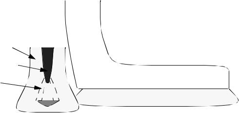
•Gas tungsten arc welding,
-gas is used to cover the tip of the torch, electrode and workpiece.
•The torch is,
-a split copper collect holding a tungsten electrode. A nut tightens the collet and holds the electrode. The collet also serves to conduct current to the electrode.
-tubes delivers gas to the torch, and it is channeled to the electrode in such a way as to ensure uniform coverage.
•Gas cups are,
-Ceramic, metals or high temperature glass is used to direct the gas about the electrode. The size typically effects the gas consumption.
•An optional trailing shield focuses gas on the now welded joint, to allow proper cooling time.
|
|
Torch |
|
|
Primary |
|
|
|
|
Gas Shield |
|
|
|
|
Electrode |
|
|
Trailing |
|
|
|
|
|
|
Arc |
|
|
Gas Shield |
|
|
|
|||
|
|
|
||
|
|
|
|
|
|
|
|
|
|
|
|
|
|
|
|
|
|
|
|
|
|
|
|
|
•The electrode stickout (or electrode extension) is the distance that the electrode protrudes out the end of the collet. A larger stickout is proportional to the energy delivered, and the size of the gascap, and it allows better visibility of the work.
•A gas lens can be used to focus/balance the flow of gases, it can be used without a gas cup, or with one to improve gas coverage.
•Gas backups are placed on the back of the weld seam, purging is used when the back of the weld is enclosed (eg tubes).
•Typical welding parameters,