

Chapter 5 - MPLAB
5.8 Toolbar
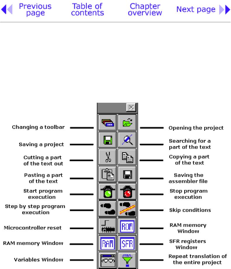
Since MPLAB has more than one component, each of the components has its own toolbar. However, there is a toolbar which is some sort of a combination of all toolbars, and can serve as a common toolbar. This toolbar is enough for our needs, and it will be explained in more detail. In the picture below, we can see a toolbar we need with a brief explanation of each icon. Because of the limited format of this book, this toolbar is shown as a hanging toolbar. Generally, it is placed horizontally below the menu, over the entire length of the screen.
Universal toolbar with brief explanations of the icons
http://www.mikroelektronika.co.yu/english/books/5_08Poglavlje.htm (1 of 3) [30/12/2001 16:54:16]
Chapter 5 - MPLAB
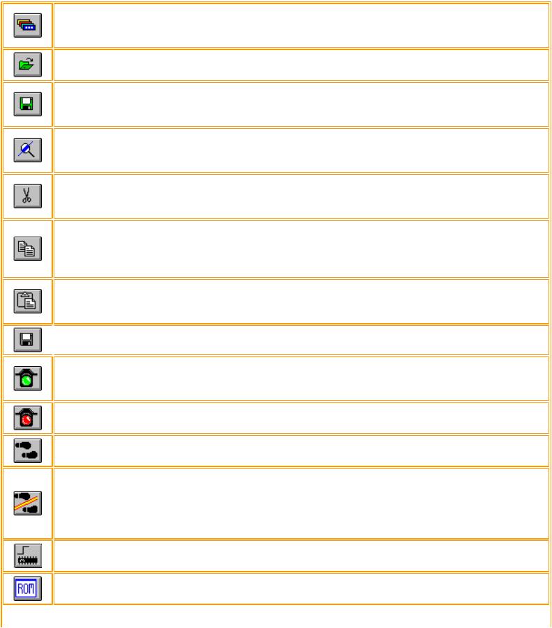
Meaning of icons in a toolbar
If the current toolbar for some reason does not respond to a click on this icon, the next one appears. Changeover is repeated so that on the fourth click we will get the same toolbar again.
Icon for opening a project. Project opened in this way contains all screen adjustments and adjustment of all elements which are crucial to the current project.
Icon for saving a project. Saved project will keep all window adjustments and all parameter adjustments. When we read in a program again, everything will return to the screen as when the project was closed.
Searching for a part of the program, or words is operation we need when searching through bigger assembler or other programs. By using it, we can find quickly a part of the program, label, macro, etc.
Cutting a part of the text out. This one and the following three icons are standard in all programs that deal with processing textual files. Since each program is actually a common text file, those operations are useful.
Copying a part of the text. There is a difference between this one and the previous icon. With cut operation, when you cut a part of the text out, it disappears from the screen (and from a program) and is copied afterwards. But with copy operation, text is copied but not cut out, and it remains on the screen.
When a part of the text is copied, it is moved into a part of the memory which serves for transferring data in Windows operational system. Later, by clicking on this icon it can be 'pasted' in the text where the cursor is.
 Saving a program (assembler file).
Start program execution in full speed. It is recognized by appearance of a yellow status line. With this kind of program execution, simulator executes a program in full speed until it is interrupted by clicking on the red traffic light icon.
Stop program execution in full speed. After clicking on this icon, status line becomes gray again, and program execution can continue step by step.
Step by step program execution. By clicking on this icon, we begin executing an instruction from the next program line in relation to the current one.
Skip requirements. Since simulator is still a software simulation of real work, it is possible to simply skip over some program requirements. This is especially handy with instructions which are waiting for some requirement following which program can proceed further. That part of the program which follows a requirement is the part that's interesting to a programmer.
Resetting a microcontroller. By clicking on this icon, program counter is positioned at the beginning of a program and simulation can start.
By clicking on this icon we get a window with a program, but this time as program memory where we can see which instruction is found at which address.
http://www.mikroelektronika.co.yu/english/books/5_08Poglavlje.htm (2 of 3) [30/12/2001 16:54:16]
Chapter 5 - MPLAB
With the help of this icon we get a window with the contents of RAM memory of a microcontroller.
By clicking on this icon, window with SFR register appears. Since SFR registers are used in every program, it is recommended that in simulator this window is always active.
If a program contains variables whose values we need to keep track of (ex. counter), a window needs to be added for each of them, which is done by using this icon.
When certain errors in a program are noticed during simulation process, program has to be corrected. Since simulator uses HEX file as its input, so we need to translate a program again so that all changes would be transferred to a simulator. By clicking on this icon, entire project is translated again, and we get the newest version of HEX file for the simulator.
© Copyright 1999. mikroElektronika. All Rights Reserved. For any comments contact webmaster.
http://www.mikroelektronika.co.yu/english/books/5_08Poglavlje.htm (3 of 3) [30/12/2001 16:54:16]

Chapter 6 - Samples
CHAPTER 6
Samples
Introduction
6.1 Supplying the microcontroller
6.2 Macros used in programs
●Macros WAIT, WAITX
●Macro PRINT
6.3 Samples
●LED diodes
●Keyboard
●Optocoupler
Optocouplering the input lines
Optocouplering the output lines
●Relays
●Generating a sound
●Shift registers
Input shift register
Output shift register
●7-segment Displays (multiplexing)
●LCD display
●12-bit AD converter
●Serial communication
Introduction
http://www.mikroelektronika.co.yu/english/books/6_01Poglavlje.htm (1 of 3) [30/12/2001 16:54:17]
Chapter 6 - Samples
Examples given in this chapter will show you how to connect the PIC microcontroller with other peripheral components or devices when developing your own microcontroller system. Each example contains detailed description of the hardware part with electrical outline and comments about the program. All programs can be taken directly from the from copied from 'MikroElektronika' internet presentation.
6.1 Supplying the microcontroller
Generally speaking, the correct voltage supply is of utmost importance for the proper functioning of the microcontroller system. It can easily be compared to a man breathing in the air. It is more likely that a man who is breathing in fresh air will live longer than a man who lives in a polluted environment.
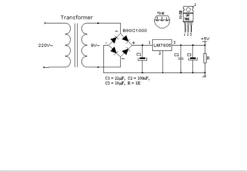
For a proper function of any microcontroller, it is necessary to provide a stable source of supply, a sure reset when you turn it on and an oscillator. According to technical specifications by the maker of PIC microcontroller, supply voltage should move between 2.0V to 6.0V in all versions. The simplest solution to the source of supply is using the voltage stabilizer LM7805 which gives stable +5V on its output. One such source is shown in the picture below.
In order to function properly, or in order to have stable 5V at the output (pin 3), input voltage on pin 1 of LM7805 should be between 7V through 24V. Depending on current consumption of device we will use the appropriate type of voltage stabilizer LM7805. There are several versions of LM7805. For electricity consumption of up to 1A we should use the version in TO-220 housing with the capability of additional cooling. If the total consumption is 50mA, we can use 78L05 (stabilizer version in small TO - 92 packaging for electricity of up to 100mA).
http://www.mikroelektronika.co.yu/english/books/6_01Poglavlje.htm (2 of 3) [30/12/2001 16:54:17]

Chapter 6 - Samples
© Copyright 1999. mikroElektronika. All Rights Reserved. For any comments contact webmaster.
http://www.mikroelektronika.co.yu/english/books/6_01Poglavlje.htm (3 of 3) [30/12/2001 16:54:17]