

SHURE microphone techniques
.pdfStereo
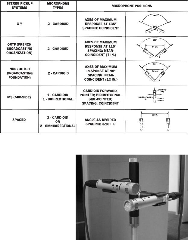
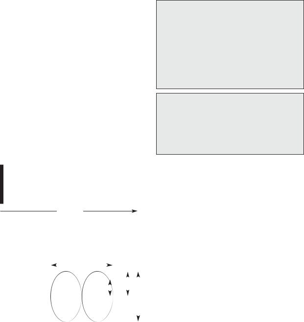
Stereo Microphone Techniques – One of the most popular specialized microphone techniques is stereo miking. This use of two or more microphones to create a stereo image will often give depth and spatial placement to an instrument or overall recording. There are a number of different methods for stereo. Three of the most popular are the spaced pair (A/B), the coincident or near-coincident pair (X-Y configuration), and the Mid-Side (M-S) technique.
The spaced pair |
|
|
|
sound |
(A/B) technique |
|
|
|
|
|
|
|
source |
|
uses two cardioid or |
|
|
|
|
omni directional |
|
|
|
|
microphones spaced |
|
|
|
|
3 - 10 feet apart |
|
|
|
|
from each other |
|
|
|
|
panned in left/right |
|
|
|
|
configuration to |
|
|
|
|
capture the stereo |
|
|
|
|
image of an |
|
|
|
|
ensemble or |
|
|
|
|
instrument. |
|
|
|
|
Effective stereo |
|
A/B top view |
|
|
|
|
|
||
separation is very |
|
|
|
|
wide. The distance |
|
|
|
|
between the two microphones is dependent on the physical size of the sound source. For instance, if two mics are placed ten feet apart to record an acoustic guitar; the guitar will appear in the center of the stereo image. This is probably too much spacing for such a small sound source. A closer, narrower mic placement should be used in this situation.
The drawback to A/B stereo is the potential for undesirable phase cancellation of the signals from the microphones. Due to the relatively large distance between the microphones and the resulting difference of sound arrival times at the microphones, phase cancellations and summing may be occurring. A mono reference source can be used to check for phase problems. When the program is switched to mono and frequencies jump out or fall out of
Microphone Techniques
for RECORDING
the sound, you can |
|
assume that there |
|
is phase problem. |
|
This may be a |
|
serious problem |
|
if your recording is |
|
going to be heard |
|
in mono as is typical |
X-Y top view |
in broadcast or |
|
soundtrack playback. |
|
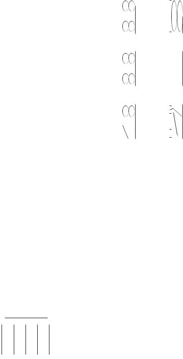
The X-Y technique uses two cardioid microphones of the same type and manufacture with the two mic capsules placed either as close as possible (coincident) or within 12 inches of each other (near-coincident) and facing each other at an angle ranging from 90 - 135 degrees, depending on the size of the sound source and the particular sound desired. The pair is placed with the center of the two mics facing directly at the sound source and panned left and right.
Due to the small distance between the microphones, sound arrives at the mics at nearly the same time, reducing (near coincident) or eliminating (coincident) the possible phase problems of the A/B techniques. The stereo separation of this technique is good but may be limited if the sound source is extremely wide. Mono compatibility is fair (near-coincident) to excellent (coincident).
The M-S or Mid-Side stereo technique involves a cardioid mic element and a bi-directional mic element, usually housed in a single case, mounted in a coincident arrangement. The cardioid (mid) faces directly at the source and picks up primarily on-axis sound while the bi-directional (side) faces left and right and picks up off-axis sound. The two signals are combined via the M-S matrix to give a variable controlled stereo image. By adjusting the level of mid versus side signals, a narrower or wider image can be created without moving the microphone. This technique is completely mono-compatible and is widely used in broadcast and film applications.
21
Microphone Techniques
for RECORDING
(see image 12)
Stereo Microphone Techniques
|
Image 12: Example of “X-Y” stereo miking technique |
22 |
using Shure A27M stereo microphone adapter |
Microphone Techniques
for RECORDING
Introduction
The world of studio recording is much different from that of live sound reinforcement, but the fundamental characteristics of the microphones and sound are the same. It is the ability to isolate individual instruments that gives a greater element of control and freedom for creativity in the studio. Since there are no live loudspeakers, feedback is not an issue. The natural sound of the instrument may be the desired effect, or the sound source can be manipulated into a sound never heard in the natural acoustic world.
In order to achieve the desired result it is useful to understand some of the important characteristics of microphones, musical instruments, and acoustics.
Section Two
23
Microphone Techniques
for RECORDING
SECTION TWO
Microphone Characteristics
There are three main considerations when choosing a microphone for recording applications: operating principle, frequency response, and directionality.
Operating Principle – A microphone is an example of a transducer, a device which changes energy from one form into another, in this case from acoustic into electrical. The type of transducer is defined by the operating principle. In the current era of recording, the two primary operating principles used in microphone design are the dynamic and the condenser.
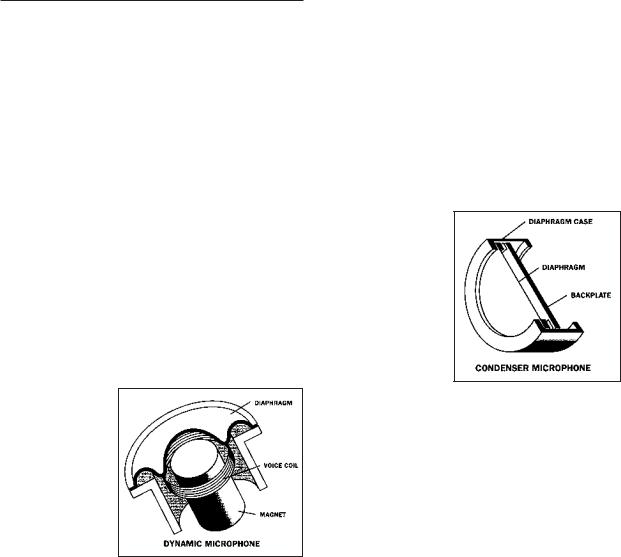
Dynamic microphone elements are made up of a diaphragm, voice coil, and magnet which form a sound-driven electrical generator. Sound waves move the diaphragm/voice coil in a magnetic field to generate the electrical equivalent of the acoustic sound wave. The signal from the dynamic element can be used directly, without the need for additional circuitry. This design is extremely rugged, has good sensitivity and can handle the loudest possible sound pressure levels without distortion.
The dynamic has some limitations at extreme high and low frequencies. To compensate, small resonant chambers are often used to extend the frequency range of dynamic microphones.
Ribbon microphone elements, a variation of the dynamic microphone operating principle, consist of a thin piece of metal, typically corrugated aluminum, suspended between two magnetic pole pieces. As with moving-coil dynamics, no additional circuitry or powering is necessary for operation, however, the output of ribbon microphones tends to be quite low. Depending on the gain of the mixer or recording device to which the microphone is connected, additional pre-amplification may be necessary. Note that ribbon microphones are not as rugged as moving-coil dynamic microphones. The ribbon element itself is typically no more than a few microns thick, and can be deformed by a strong blast of air, or by blowing into the
microphone. Also, phantom power applied to the ribbon microphone could be harmful. Ribbon microphones are highly regarded in studio recording for their “warmth” and good low frequency response.
Condenser microphone elements use a conductive diaphragm and an electrically charged backplate to form a sound-sensitive “condenser” (capacitor). Sound waves move the diaphragm in an electric field to create the electrical signal. In order to use this signal from the element, all condensers have active electronic circuitry, (often referred to as the “preamp”) either built into the microphone or in a separate pack. This means that condenser microphones require phantom power or a battery to operate. (For
a detailed explanation of “phantom power”, see the sidebar.)
However, the condenser design allows for smaller mic elements, higher sensitivity and is inherently capable of smooth response across a very wide frequency range.
The main limitations of a condenser microphone relate to its electronics. These circuits can handle a specified maximum signal level from the condenser element, so a condenser mic has a maximum sound level before its output starts to be distorted. Some condensers have switchable pads or attenuators between the element and the electronics to allow them to handle higher sound levels. If you hear distortion when using a condenser microphone close to a very loud sound source, first make sure that the mixer input itself is not being overloaded. If not, switch in the attenuator in the mic (if equipped), move the mic farther away, or use a mic that can handle a higher level. In any case, the microphone will not be damaged by excess level.
A second side effect of the condenser/electronics design is that it generates a certain amount of electrical noise (self-noise) which may be heard as “hiss” when recording very quiet sources at high gain settings. Higher quality condenser mics have very low self-noise, a desirable characteristic for this type of recording application.
Most modern condenser microphones use solid state components for the internal circuitry, but older designs employed vacuum tubes (also known as “valves”) for this purpose. The subjective qualities imparted by vacuum
24

Microphone Techniques
for RECORDING
tube electronics, often described as “warmth” or “smoothness,” have led to a resurgence in the popularity of vacuum tube-based condenser microphones. These sonic advantages come at the expense of higher self-noise and fragility. Vacuum tubes typically have a limited life span, and eventually need to be replaced. Most vacuum tube microphones require an external power supply, as standard 48V phantom power is not sufficient. Some power supplies offer the ability to switch polar patterns remotely on microphones that feature dual-diaphragms (see Directionality for a discussion of microphone polar patterns).
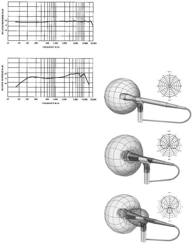
Frequency response – The variation in output level or sensitivity of a microphone over its useable range from lowest to highest frequency.
Virtually all microphone manufacturers will list the frequency response of their microphones as a range, for example 20 - 20,000Hz. This is usually illustrated with a graph that indicates relative amplitude at each frequency. The graph has the frequency in Hz on the x-axis and relative response in decibels on the y-axis.
A microphone whose response is equal at all frequencies is said to have a “flat” frequency response. These microphones typically have a wide frequency range. Flat response microphones tend to be used to reproduce sound sources without coloring the original source. This is usually desired in reproducing instruments such as acoustic guitars or pianos. It is also common for stereo miking techniques and distant miking techniques.
A microphone whose response has peaks or dips in certain frequency areas is said to have a “shaped” response. This response is designed to enhance a frequency range that is specific to a given sound source. For instance, a microphone may have a peak in the 2-10Khz range to enhance the intelligibility or presence of vocals. This shape is said to have a “presence peak”. A microphone’s response may also be reduced at other frequencies. One example of this is a low frequency roll-off to reduce unwanted “boominess”.
Although dynamic microphones and condenser microphones may have similar published frequency response specifications their sound qualities can be quite different. A primary aspect of this difference is in their transient response. See the appendix for an explanation of this characteristic.
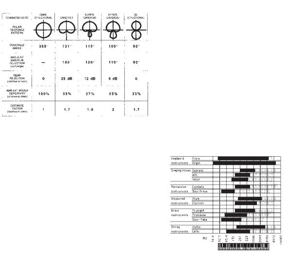
Directionality – The sensitivity to sound relative to the direction or angle of arrival at the microphone.
Directionality is usually plotted on a graph referred to as a polar pattern. The polar pattern shows the variation in sensitivity 360 degrees around the microphone, assuming that the microphone is in the center and 0 degrees represents the front or on-axis direction of the microphone.
There are a number of different directional patterns designed into microphones. The three basic patterns are omnidirectional, unidirectional, and bidirectional.
The omnidirectional microphone has equal response at all angles. Its “coverage” or pickup angle is a full 360 degrees. This type of microphone can be used if more room ambience is desired. For example, when using an “omni”, the balance of direct and ambient sound depends on the distance of the microphone from the instrument, and can be adjusted to the desired effect.
Phantom Power
Phantom power is a DC voltage (usually 12-48 volts) used to power the electronics of a condenser microphone. For some (non-electret) condensers it may also be used to provide the polarizing voltage for the element itself. This voltage is supplied through the microphone cable by a mixer equipped with phantom power or by some type of in-line external source. The voltage is equal on Pin 2 and Pin 3 of a typical balanced, XLR-type connector. For a 48 volt phantom source, for example, Pin 2 is 48 VDC and Pin 3 is 48 VDC, both with respect to Pin 1 which is ground (shield).
Because the voltage is exactly the same on Pin 2 and Pin 3, phantom power will have no effect on balanced dynamic microphones: no current will flow since there is no voltage difference across the output. In fact, phantom power supplies have current limiting which will prevent damage to a dynamic microphone even if it is shorted or miswired. In general, balanced dynamic microphones can be connected to phantom powered mixer inputs with no problem.
25
Microphone Techniques
for RECORDING
Flat frequency response drawing
Shaped frequency response drawing
The unidirectional microphone is most sensitive to sound arriving from one particular direction and is less sensitive at other directions. The most common type is a cardioid (heart-shaped) response. This has full sensitivity at 0 degrees (on-axis) and is least sensitive at 180 degrees (off-axis). Unidirectional microphones are used to isolate the desired on-axis sound from unwanted off-axis sound. In addition, the cardioid mic picks up only about one-third as much ambient sound as an omni.
For example, the use of a cardioid microphone for a guitar amplifier, which is in the same room as the drum set, is one way to reduce the bleed-through of drums on to the recorded guitar track. The mic is aimed toward the amplifier and away from the drums. If the undesired sound source is extremely loud (as drums often are), other isolation techniques may be necessary.
Unidirectional microphones are available with several variations of the cardioid pattern. Two of these are the supercardioid and hypercardioid.
Both patterns offer narrower front pickup angles than the cardioid (115 degrees for the supercardioid and 105 degrees for the hypercardioid) and also greater rejection of ambient sound. While the cardioid is least sensitive at the rear (180 degrees off-axis), the least sensitive direction is at
125 degrees for the supercardioid and 110 degrees for the hypercardioid. When placed properly they can provide more “focused” pickup and less room ambience than the cardioid pattern, but they have less rejection at the rear: -12 dB for the supercardioid and only -6 dB for the hypercardioid.
The bidirectional microphone has full response at both 0 degrees (front) and at 180 degrees (back). It has its least response at the sides. The coverage or pickup angle is only about 90 degrees at the front (or the rear). It has the same amount of ambient pickup as the cardioid. This mic could be used for picking up two sound sources such as two vocalists facing each other. It is also used in certain stereo techniques.
Omnidirectional
Cardioid (unidirectional)
Supercardioid
26
Microphone Techniques
for RECORDING
Microphone polar patterns compared
Other directional-related microphone characteristics:
Ambient sound sensitivity – Since unidirectional microphones are less sensitive to off-axis sound than omnidirectional types, they pick up less overall ambient or room sound. Unidirectional mics should be used to control ambient noise pickup to get a “cleaner” recording.
Distance factor – Since directional microphones have more rejection of off-axis sound than omnidirectional types, they may be used at greater distances from a sound source and still achieve the same balance between the direct sound and background or ambient sound. An omnidirectional microphone will pick up more room (ambient) sound than a unidirectional microphone at the same distance. An omni should be placed closer to the sound source than a “uni”– about half the distance – to pick up the same balance between direct sound and room sound.
Off-axis coloration – A microphone’s frequency response may not be uniform at all angles. Typically, high frequencies are most affected, which may result in an unnatural sound for off-axis instruments or room ambience.
Proximity effect – For most unidirectional types, bass response increases as the microphone is moved closer to the sound source. When miking close with unidirectional microphones (less than 1 foot), be aware of proximity effect: it may help to roll off the bass until you obtain a more natural sound. You can (1) roll off low frequencies at the mixer, (2) use a microphone designed to minimize proximity effect, (3) use a microphone with a bass roll-off switch, or (4) use an omnidirectional microphone (which does not exhibit proximity effect).
Understanding and choosing the frequency response and directionality of microphones are selective factors which can improve pickup of desired sound and reduce pickup of unwanted sound. This can greatly assist in achieving both natural sounding recordings and unique sounds for special applications.
Instrument Characteristics
First, let’s present a bit of background information about how instruments radiate sound. The sound from a musical instrument has a frequency output which is the range of frequencies produced and their relative amplitudes. The fundamental frequencies establish the basic pitch, while the harmonic frequencies produce the timbre or characteristic tone of the instrument. Here are frequency ranges for some commonly known instruments:
Chart of instrument frequency ranges
Also, an instrument radiates different frequencies at different levels in every direction, and each part of an instrument produces a different timbre. This is the directional output of an instrument. You can partly control the recorded tonal balance of an instrument by adjusting the microphone position relative to it. The fact that low frequencies tend to be omnidirectional while higher frequencies tend to be more directional is a basic audio principle to keep in mind.
Most acoustic instruments are designed to sound best at a distance (say, two or more feet away). The sounds of the various parts of the instrument combine into a complete audio picture at some distance from the instrument. So, a microphone placed at that distance will pick up a “natural” or well-balanced tone quality. On the other hand, a microphone placed close to the instrument emphasizes the part of the instrument that the microphone is near. The sound picked up very close may or may not be the sound you wish to capture in the recording.
27
Microphone Techniques
for RECORDING
Acoustic Characteristics
Since room acoustics have been mentioned repeatedly, here is a brief introduction to some basic factors involved in acoustics.
Sound Waves – Sound waves consist of pressure variations traveling through the air. When the sound wave travels, it compresses air molecules together at one point. This is called the high pressure zone or positive component(+). After the compression, an expansion of molecules occurs. This is the low pressure zone or negative component(-). This process continues along the path of the sound wave until its energy becomes too weak to hear. If you could view the sound wave of a pure tone traveling through air, it would appear as a smooth, regular variation of pressure that could be drawn as a sine wave. The diagram shows the relationship of the air molecules and a sine wave.
|
rarefaction |
|
compression |
rarefaction |
|
compression |
|
|
|
|
|
|
|
|
|
............................ ............................ ............................ ............................ ............................ ............................ ............................ ............................ ............................ ............................ .................................................................................... ........................................................ ........................................................ ........................................................ ........................................................ ........................................................ ........................................................ ................................................................................................................................................................................................................................................................................................................................................................................................................................................................................................................................................................................................................................................................................................ |
|||||||
wave motion
Frequency, Wavelength, and the Speed of Sound –
The frequency of a sound wave indicates the rate of pressure variations or cycles. One cycle is a change from high pressure
to low pressure |
|
|
|
|
one cycle or one period |
|
|
|
|
|
|
|
|
|
|
|
|
|
||||
|
|
|
|
|
|
|
|
|
|
|
|
|
|
|
|
|||||||
and back to high |
|
|
|
|
|
|
|
|
|
|
|
|
|
|
|
|
|
|
|
|
|
|
|
|
|
|
|
|
|
|
|
|
|
|
|
|
|
|
|
|
|
|
|
||
|
|
|
|
|
|
|
|
|
rms |
|
|
|
|
|
|
|
|
|
|
|||
pressure. The |
|
|
|
|
|
|
|
|
|
|
|
|
|
|
|
|
|
|
|
|||
|
|
|
|
|
|
|
|
|
|
|
|
|
|
peak |
|
|
|
|||||
number of cycles |
|
|
|
|
|
|
|
|
|
|
|
|
|
|
|
|
|
|||||
|
|
|
|
|
|
|
|
|
|
|
|
|
|
|
|
|
||||||
|
|
|
|
|
|
|
|
|
|
|
|
|
|
|
|
|
|
|
|
|
||
|
|
|
|
|
|
|
|
|
|
|
|
|
|
|
|
|
|
|
|
|
||
per second is |
|
|
|
|
|
|
|
|
|
|
|
|
|
|
|
|
|
|
|
|
|
|
|
|
|
|
|
|
|
|
|
|
|
|
|
|
|
|
|
|
|
|
|
|
|
called Hertz, |
|
|
|
|
|
|
|
|
|
|
|
|
|
|
|
|
|
|
|
|
|
|
|
|
|
|
|
|
|
|
|
|
|
|
|
|
|
|
peak-to-peak |
||||||
abbreviated “Hz.” |
|
|
|
|
|
|
|
|
|
|
|
|
|
|
|
|
||||||
|
|
|
|
|
|
|
|
|
|
|
|
|
|
|
|
|
|
|
|
|
||
|
|
|
|
|
|
|
|
|
|
|
|
|
|
|
|
|
|
|
|
|
||
So, a 1,000Hz |
|
|
|
|
|
|
|
|
|
|
|
|
|
|
|
|
|
|
|
|
|
|
|
|
|
|
|
|
|
|
|
|
|
|
|
|
|
|
|
|
|
|
|
||
tone has 1,000 |
|
|
|
|
|
|
|
|
|
|
|
|
|
|
|
|
|
|
|
|
|
|
cycles per second. |
|
|
|
|
|
Wave amplitude |
||||||||||||||||
The wavelength of a sound is the physical distance from the start of one cycle to the start of the next cycle. Wavelength is related to frequency by the speed of sound. The speed of sound in air is 1130 feet per second or 344 meters/second. The speed of sound is constant no matter what the frequency. You can determine the wavelength of a sound wave of any frequency if you understand these relationships:
The Wave Equation: c = f • l speed of sound = frequency • wavelength
or
speed of sound frequency
for a 500Hz sound wave:
wavelength = 1,130 feet per second 500Hz
wavelength = 2.26 feet
Approximate wavelengths of common frequencies:
100 Hz: about 10 feet
1000 Hz: about 1 foot
10,000 Hz: about 1 inch
Loudness –
The fluctuation of air pressure created by sound is a change above and below normal atmospheric pressure. This is what the human ear responds to.
The varying amount of pressure of the air molecules compressing and
expanding is related to the apparent
loudness at the
human ear. The greater the pressure change, the louder the sound. Under ideal conditions the human ear can sense a pressure change as small as .0002 microbar. One microbar is equal to one millionth of atmospheric pressure. The threshold of pain is about 200 microbar. Obviously, the human ear responds to a wide range of amplitude of sound. This amplitude range is more commonly referred to in decibels. Sound Pressure Level (dB SPL), relative to
.0002 microbar (0dB SPL). 0 dB SPL is the threshold of hearing and 120 dB SPL is the threshold of pain. 1 dB is about the smallest change in SPL that can be heard. A 3 dB change is generally noticeable, while a 6 dB change is very noticeable. A 10 dB SPL increase is perceived to be twice as loud!
28

Microphone Techniques
for RECORDING
Sound Transmission – It is important to remember that sound transmission does not normally happen in a completely controlled environment. In a recording studio, though, it is possible to separate or isolate the sounds being recorded. The best way to do this is to put the different sound sources in different rooms. This provides almost complete isolation and control of the sound from the voice or instrument. Unfortunately, multiple rooms are not always an option in studios, and even one sound source in a room by itself is subject to the effects of the walls, floor, ceiling and various isolation barriers. All of these effects can alter the sound before it actually arrives at the microphone.
In the study of acoustics there are three basic ways in which sound is altered by its environment:
1. Reflection – A sound wave can be reflected by a surface or other object if the object is physically as large or larger than the wavelength of the sound. Because low-frequency sounds have long wavelengths, they can only be reflected by large objects. Higher frequencies can be reflected by smaller objects and surfaces. The reflected sound will have a different frequency characteristic than the direct sound if all sounds are not reflected equally. Reflection is also the source of echo, reverb, and standing waves:
Echo occurs when an indirect sound is delayed long enough (by a distant reflective surface) to be heard by the listener as a distinct repetition of the direct sound.
Reverberation consists of many reflections of a sound, maintaining the sound in a room for a time even after the direct sound has stopped.
Standing waves in a room occur for certain frequencies related to the distance between parallel walls. The original sound and the reflected sound will begin to reinforce each other when the wavelength is equal to the distance between two walls. Typically, this happens at low frequencies due to their longer wavelengths and the difficulty of absorbing them.
2. Refraction – The bending of a sound wave as it passes through some change in the density of the transmission environment. This change may be due to physical objects, such as blankets hung for isolation or thin gobos, or it may be due to atmospheric effects such as wind or temperature gradients. These effects are not noticeable in a studio environment.
3. Diffraction – A sound wave will typically bend around obstacles in its path which are smaller than its wavelength. Because a low frequency sound wave is much longer than a high frequency wave, low frequencies will bend around objects that high frequencies cannot. The effect is that high frequencies are more easily blocked or absorbed while low frequencies are essentially omnidirectional. When isolating two instruments in one room with a gobo as an acoustic barrier, it is possible to notice the individual instruments are “muddy” in the low end response. This may be due to diffraction of low frequencies around the acoustic barrier.
Applications Tip:
Absorption (beware of carpets!)
When building a project studio or small commercial studio, it is usually necessary to do some sound treatment to the walls and possibly build some isolating gobos for recording purposes. Many small studios assume they can save money and achieve the desired absorption effect by using inexpensive carpet. This is a bad assumption.
Absorption is the changing of sound energy into heat as it tries to pass through some material. Different materials have different absorption effects at multiple frequencies. Each material is measured with an absorption coefficient ranging between 0-1 (sabins). This can be thought of as the percentage of sound that will be absorbed.
For instance: a material may have an absorption coefficient of
.67 at 1,000 Hz. This would mean the material absorbs 67% of the 1,000 Hz frequencies applied to it.
Here is a chart showing the advantages of acoustic foam over bare walls or carpeting.
29
Microphone Techniques
for RECORDING
Direct vs. Ambient Sound – A very important property of direct sound is that it becomes weaker as it travels away from the sound source, at a rate controlled by the inverse-square law. When the distance from a sound source doubles, the sound level decreases by 6dB. This is a noticeable audible decrease. For example, if the sound from a guitar amplifier is 100 dB SPL at 1 ft. from the cabinet it will be 94 dB at 2 ft., 88 dB at 4 ft., 82 dB at 8 ft., etc. When the distance is cut in half the sound level increases by 6dB: It will be 106 dB at 6 inches and 112 dB at 3 inches.
On the other hand, the ambient sound in a room is at nearly the same level throughout the room. This is because the ambient sound has been reflected many times within the room until it is essentially non-directional. Reverberation is an example of non-directional sound.
This is why the ambient sound of the room will become increasingly apparent as a microphone is placed further away from the direct sound source. The amount of direct sound relative to ambient sound can be controlled by the distance of the microphone to the sound source and to a lesser degree by the polar pattern of the mic.
However, if the microphone is placed beyond a certain distance from the sound source, the ambient sound will begin to dominate the recording and the desired balance may not be possible to achieve, no matter what type of mic is used. This is called the “critical distance” and becomes shorter as the ambient noise and reverberation increase, forcing closer placement of the microphone to the source.
Phase relationships and interference effects – The phase of a single frequency sound wave is always described
relative to the starting point of the wave or |
0 degrees. |
|||||||||||||
The pressure change is also |
|
|
|
|
|
|
|
|
|
|
|
|
|
|
zero at this point. The peak |
|
▲ |
one cycle or one period |
▲ |
|
|||||||||
|
|
|||||||||||||
|
|
|
|
|
|
|
|
|||||||
of the high pressure zone is at |
|
|
|
|
|
|
|
|
|
|
|
|
|
|
|
|
|
|
|
|
|
|
|
|
|
|
|
||
90 degrees, and the pressure |
|
|
|
|
|
|
|
|
|
|
|
|
|
|
change falls to zero again at |
|
|
|
|
|
|
|
|
|
|
|
|
|
|
|
|
|
|
|
|
|
|
|
|
|
|
|
||
180 degrees. The peak of the |
|
|
|
|
|
|
|
|
|
|
|
|
|
|
low pressure zone is at 270 |
|
|
|
|
|
|
|
|
|
|
|
|
|
|
|
00 |
|
900 |
|
1800 |
2700 |
3600 |
|
||||||
degrees, and the pressure |
|
|
|
|
|
|
|
|
|
|
|
|
|
|
|
|
|
|
|
|
|
|
|
|
|
|
|
|
|
change rises to zero at 360 |
|
Sound pressure wave |
||||||||||||
degrees for the start of the |
|
|
|
|
|
|
|
|
|
|
|
|
|
|
next cycle. |
|
|
|
|
|
|
|
|
|
|
|
|
|
|
|
+1 |
|
|
|
|
|
|
|
|
|
+2 |
|
|
|
|
|
|
|
|
0 |
|
|
|
|
|
|
|
|
|
|
|
|
|
|
|
|
|
|
|
|
|
|
|
|
|
|
|
|
|
|
|
|
|
|
||
“in-phase” |
-1 |
|
|
|
|
|
+ |
= 0 |
|
|
|
|
|
|
||||
+1 |
|
|
|
|
|
|
|
|
|
|
|
|||||||
|
|
|
|
|
|
|||||||||||||
|
|
|
|
|
|
|
|
|
|
|
||||||||
|
|
|
|
|
||||||||||||||
|
|
|
|
|
|
|
|
|||||||||||
|
0 |
|
|
|
|
|
|
|
|
|
|
|
|
|
|
|
|
|
|
|
|
|
|
|
|
|
|
|
|
|
|
|
|
|
|
||
a |
-1 |
|
|
|
|
|
|
|
|
|
-2 |
|
|
|
|
|
|
|
+1 |
|
|
|
|
|
|
|
|
|
|
|
|
|
|
|
|
|
|
|
|
|
|
|
|
|
|
|
|
|
|
|
|
|
|
|
||
|
|
|
|
|
|
|
|
|
|
|
|
|
|
|
|
|
|
|
|
|
|
|
|
|
|
|
|
|
|
|
|
|
|
|
|
|
|
|
|
|
|
|
|
|
|
|
|
|
|
|
|
|
|
|
|
|
|
|
|
|
|
|
|
|
|
|
|
|
|
|
|
|
|
||
”1800 out |
0 |
|
|
|
|
|
|
|
|
|
|
|
|
|
|
|
|
|
|
|
|
|
|
|
|
|
|
|
|
|
|
|
|
|
|
||
-1 |
|
|
|
+ |
= 0 |
|
|
|
|
|
|
|||||||
|
|
|
|
|
|
|
|
|
|
|||||||||
of phase” |
+1 |
|
|
|
|
|
|
|
|
|
||||||||
|
|
|
|
|
|
|
|
|||||||||||
|
0 |
|
|
|
|
|
|
|
|
|
|
|
|
|
|
|
|
|
|
|
|
|
|
|
|
|
|
|
|
|
|
|
|
|
|
||
b |
-1 |
|
|
|
|
|
|
|
|
|
|
|
|
|
|
|
|
|
+1 |
|
|
|
|
|
|
|
|
|
+2 |
|
|
|
|
|
|
||
|
|
|
|
|
|
|
|
|
|
|
|
|
|
|
|
|||
|
|
|
|
|
|
|
|
|
|
|
|
|
|
|
|
|||
|
|
|
|
|
|
|
|
|
|
|
|
|
|
|
|
|||
|
|
|
|
|
|
|
|
|
|
|
|
|
|
|
||||
|
0 |
|
|
|
|
|
|
|
|
|
|
|
|
|
|
|
|
|
|
|
|
|
|
|
|
|
|
+1 |
|
|
|
|
|
|
|||
|
|
|
|
|
|
|
|
|
|
|
|
|
|
|
||||
|
-1 |
|
|
|
|
|
|
|
|
|
|
|
|
|
|
|
||
“phase shifts” |
|
|
|
|
|
|
+ |
= 0 |
|
|
|
|
|
|
||||
+1 |
|
|
|
|
|
|
|
|
|
|||||||||
|
|
|
|
|
|
|
|
|
||||||||||
|
|
|
|
|
|
|
|
|||||||||||
|
|
|
|
|
|
|
|
|
||||||||||
|
0 |
|
|
|
|
|
|
|
|
|
-1 |
|
|
|
|
|
|
|
|
|
|
|
|
|
|
|
|
|
|
|
|
|
|
|
|
|
|
|
-1 |
|
|
|
|
|
|
|
|
|
-2 |
|
|
|
|
|
|
|
c
Phase relationships
Two identical sound waves starting at the same point in time are called “in-phase” and will sum together creating a single wave with double the amplitude but otherwise identical to the original waves. Two identical sound waves with one wave’s starting point occurring at the 180degree point of the other wave are said to be “out of phase”, and the two waves will cancel each other completely. When two sound waves of the same single frequency but different starting points are combined, the resulting wave as said to have “phase shift” or an apparent starting point somewhere between the original starting points. This new wave will have the same frequency as the original waves but will have increased or decreased amplitude depending on the degree of phase difference. Phase shift, in this case, indicates that the 0 degree points of two identical waves are not the same.
Most soundwaves are not a single frequency but are made up of many frequencies. When identical multiplefrequency soundwaves combine, there are three possibilities for the resulting wave: a doubling of amplitude at all frequencies if the waves are “in phase”, a complete cancellation at all frequencies if the waves are 180 degrees “out of phase”, or partial cancellation and partial reinforcement at various frequencies if the waves have intermediate phase relationship.
30