

Сборник трудов конференции СПбГАСУ ч
.2.pdfРаздел 4. Лабораторные и полевые исследования грунтов и фундаментных конструкций…
Figure 11. Freezing depth with elapsed time for |
Figure 12. Heave amount with elapsed time for |
Test Sections |
Test Sections |
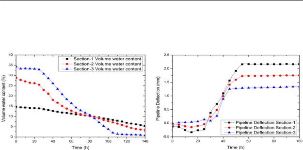
The unfrozen water in soil matrix for each test section was measured by using a TDR(Time domain reflectometer). This instrument has a probe to penetrate into soil ground and send the electric wave. The moisture content can be determine with consideration of the depth of probe penetration into soil ground and round travel time of electric wave. The transmitted rates through soil solid particle, ice, water, air void in the frozen soil are different and hence the volumetric moisture content can be determined. The amount of unfrozen water in the soil during the period of freezing contains less than 5 %, but it increases up to 9.4 % in the thawing period of spring. Figure 13 shows a results of unfrozen water content with elapsed time for three different test sections.. The Test Section 1 which consisted with decomposed granite soil shows a small amount of unfrozen water content because it is much susceptible to be frozen with comparing other two filling materials. While Test Section 3 consisted with a RPF mixed soil shows a large portion of unfrozen water in the soil matrix. In general, an amount of unfrozen water decreases with the time passing due to the influence of air temperature. The filling material of RPF mixed soil has a large portion of void, so in the last long period of time, the soil can not strain the escaping the water from soil matrix and hence amount of unfrozen water content is much less than that of other two materials
The displacements of water supply pipelines are underway with the elapsed time under the freezing temperature. In the beginning of the application of freezing temperature -15 С, the water supply pipelines are under compression load up to the elapsed time of 30 hours. This is mainly due to the forming of the ice lens from the GL-5 and this phenomenon occurs continuously until the underground temperature reaches below zero. Ladanyi (1981) reported that the volume of water increases approximately 9 % as the water becomes ice. As the ice lens is being formed around the water supply pipeline, the ground heave begins after elapsed time of 30 hours. The magnitude of frost heave on the ground surface is linearly increased and reached the ultimate level. This results are shown in Figure 14. The maximum displacement of water supply pipeline for Test Sections 1, 2, and 3 were occurred as 22.46 cm, 17.46 cm, and 13.96, respectively. It is certain that soil ground mixed with 6% of RPF shows the lowest displacement due to lack of water
221
Современные геотехнологии в строительстве и их научно-техническое сопровождение
supply by the action of capillary. Therefore, the movement of water supply pipeline is not so much and the influence to the integrity of water supply pipeline is minimized.
Figure 13. Variation of unfrozen water content |
Figure 14. Displacement of water main for test |
for each test sections |
sections |
The strain gauges were attached on the surface of water supply pipeline both on the top and bottom to measure the deformation behavior of water main by the application of freezing load. The tensile strain and compressive strain were occurred at the top and bottom of water mains in the period of fully mobilized freezing load. The displacement of water supply pipeline was predicted by numerical simulation. The results are similar to the experimental results.
5. Conclusions
The laboratory model tests of water supply pipelines under the freezing temperature were conducted. Three different bedding soils were used such as decomposed granite soil, sand, and recycled PET flake for water supply pipelines in the model soil ground. The frost penetration depth and the magnitude of heaving, deformation and strain of pipe, as well as unfrozen water content were measured with the elapsed time. Based on the experimental test results, the following conclusions are drawn
1.The RPF mixed soil gives slightly lower value of an optimum moisture content and higher maximum dry unit weight of soil compared with those results of unmixed soil. The RPF reduces the percentage of fine particles and pore water in the soil matrix also reduces. The water adsorption of RPF mixed soil shows much lower capacity comparison of sandy soil.
2. The laboratory frost heave test indicated that the optimum mixing ration of RPF is approximately 6% with the consideration of reduction of frost heave in the field as well as economical point of view.
222

Раздел 4. Лабораторные и полевые исследования грунтов и фундаментных конструкций…
3.The water supply pipeline takes a compression load in the beginning of freezing temperature and extension load in the long period of freezing temperature. The RPF mixed soil has a low frost heave as well as lower displacement of water supply pipeline compared with other filling materials
4.Based on the laboratory freezing test of water supply pipelines, the tensile strain and compressive strain were occurred at the top and bottom of water mains in the period of fully mobilized freezing load.
Acknowledgements
This research was supported by a grant (2011 Technology Innovation F01) from Construction Technology Innovation Program (CTIP) funded by Ministry of Land, Transportation and Maritime Affairs (MLTM) of Korean government.
References
1. Lee., H. I., (2002), “Be accompanied by stress corrosion cracking also causes and remedies of winter damage to the steel pipe”, Korea Infrastructure Safety Corporation,
pp.239-267.
2.Topp, G. C. and Davis, J. L. (1985), Time Domain Reflectometry (TDR) and Its Application to Irrigation Scheduling, In Advances in Irrigation, Vol. 3, Daniel Hilled(ed), Academic.
3.America Society for Testing and Material.(2007), "Standard Test Methods for Frost Heave and Thaw Weakening Susceptibility of Soils", Annual Book of ASTM Standard Designation : D 5918-06, pp. 401-412.
4.Shin, E. C., Kim B. S., Kim K. S. (2013), “Frost heaving sensitivity of recycled PET
bottles mixed soil through laboratory freezing test”. Fall Geosynthetics Conference, pp. 121-124.
5.Ladanyi, E. and Arteau, J.(1978), "Effect of Specimen Shape on Creep Response of a Frozen Sand", Intern, Symp. on Ground Freezing Soil, pp. 141-153.
6.Hong., S. S., Kim Y. S., Lee., J. G., Kang., J. M., Bae., G. J., (2010) “The Effect of
Frost Protection of Waste Materials Using the TRRL Frost-Heave Test” Kora Geoenvironmental engineering. pp. 557-562.
223

Современные геотехнологии в строительстве и их научно-техническое сопровождение
Kim D.S.1), Nguyen D. D. C. 1), Jo S.B.1)
(Department of Civil Engineering, KAIST, Daejeon 305-701, Korea)
EXPERIMENTAL AND NUMERICAL STUDY FOR OPTIMAL DESIGN OF LARGE PILED RAFT FOUNDATION
ABSTRACT
In the design of piled raft foundations, the control of total and differential settlements is crucial. This paper presents results of the experimental and the numerical study for investigating optimal design method for large piled raft foundations. Centrifuge tests were performed to verify the feasibility of a fairly optimal pile arrangement scheme in reducing settlements and induced bending moment for a large piled raft. Then, a series of numerical study were conducted using PLAXIS 3D software to study the influence of pile length, raft thickness, number of pile and horizontal and moment loads on the behaviour of a large piled raft. According to the results of the numerical study, the proposal for optimal design has been made.
Introduction
In most structures, the control of total and differential settlements is very important. In particular, differential settlements can have negative effects on a superstructure by causing an increase in the internal stress and in consequence reducing the building service life. Thus, restrictions within allowable limits are necessary. Among the various types of foundations used at present, the piled raft foundation is widely adopted as an effective total and differential settlements reducer. This foundation system consists of piles, raft, and soil, with the piles playing the main role in reducing settlements. From an economical point of view, however, the settlement of this foundation should be controlled for an economical design while still satisfying an acceptable level.
In the past, the mechanical properties that affect the total and differential settlements of a piled raft foundation were investigated by many researchers such as Fleming et al. (1992), Randolph (1994), Horikoshi and Randolph (1996), Horikoshi and Randolph (1998), Poulos (2001) and Kim et al. (2001). As a practical design, Messeturm tower in Frankfurt am Main was designed using a piled raft foundation which has more piles arranged near the edges of the raft at the diaphragm positions (Katzenbach et al. 2005). Nevertheless, there is no measured data or detailed research regarding the ability to reduce the differential settlement in this pile arrangement scheme.
This paper reports the contribution of the authors’ studies to the above issue. The experimental study (Nguyen et al. 2013) which consists of several centrifuge tests was performed to verify the feasibility of the concentrated pile arrangement of a large piled raft for reducing total and differential settlements and induced bending moment for this foundation. And, the numerical study (Nguyen et al. 2014)
224

Раздел 4. Лабораторные и полевые исследования грунтов и фундаментных конструкций…
which employs PLAXIS 3D software was conducted to investigate the methods for optimal design for a large piled raft. The results reached will be of interest to the foundation designers.
Measured and Computed Settlements of Piled Raft Foundation in Centrifuge
Models
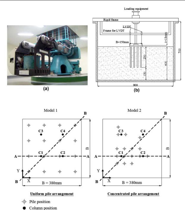
This section presents the results of the centrifuge test performed to verify the advantages of the concentrated pile arrangement method for a large piled raft subjected to column loads as well as comparisons between the measured results and the calculated results obtained by numerical simulation via PLAXIS 3D. The centrifuge tests were performed with three piled raft models, one model (model 1with a uniform pile arrangement and the others (model 2-1 and model 2-2) with a concentrated pile arrangement (Figure 1). Model 1 and model 2-1 have a flexible raft and model 2-2 has a rigid raft. Figure 2 shows the model test layout. The settlements of the rafts are monitored along two cross-sections, A-A and B-B. The bending moments of the rafts are monitored along section A-A. Four columns were used to reproduce the point loads on the foundation models. The external load is unsymmetrically applied to the raft to create differential settlement along the A-A and B-B sections. The soil is loose silica sand with a relative density of approximately 40%. The details of these centrifuge tests can be found in Nguyen et al. (2013).
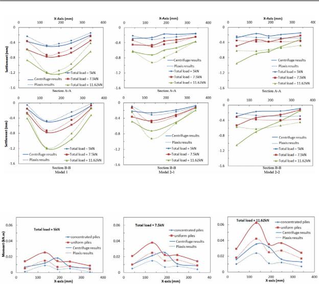
Figure 3 presents the settlements measured along the A-A and B-B sections. It can be seen that the centrifuge test data show a general trend that the total and differential settlements of the piled raft increase with the increase of the total applied load. In addition, the centrifuge results show that the total and differential settlements of the piled raft with a concentrated pile arrangement are much smaller than those of the piled raft with a uniform pile arrangement when the applied load is large.
In comparing results by centrifuge and by PLAXIS 3D, the same trend arises during the development of the differential settlement with an increase of the total load. The results of two pile arrangement cases obtained from PLAXIS 3D match those from the centrifuge tests fairly well.
Figure 4 presents the induced bending moments of the two flexible rafts along section A-A. It can be seen that the concentrated pile arrangement can also reduce the induced bending moment of the raft. The results of PLAXIS 3D also matches fairly well with the results from the centrifuge tests. From the comparison between numerical results and centrifuge test results, it can be seen that PLAXIS 3D is a reliable tool for solving piled raft foundation problem.
225
Современные геотехнологии в строительстве и их научно-техническое сопровождение
Figure 1. KOCED geotechnical centrifuge with testing system and test model set-up. (a) KOCED geotechnical centrifuge with testing system. (b) Test model set-up. (Nguyen et al. 2013)
Figure 2. Pile, column arrangement (Nguyen et al. 2013)
226
Раздел 4. Лабораторные и полевые исследования грунтов и фундаментных конструкций…
Figure 3. Comparison of the settlement between centrifuge tests and Plaxis 3D (Nguyen et al. 2013)
Figure 4. Comparison of bending moment along section A-A between centrifuge tests and Plaxis 3D (Nguyen et al. 2013)
Numerical Study for Optimal Design of Large Piled Raft via Plaxis 3D
Effects of raft thickness with optimum pile arrangement
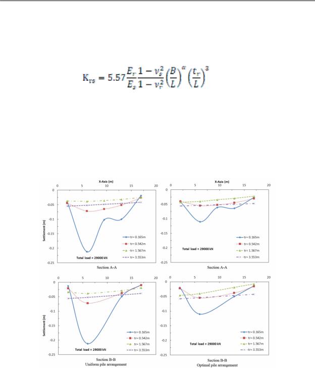
The raft thickness considerably affects its settlements and its induced bending moments. When the raft thickness increases, the differential settlement decreases. The thickness of the raft (tr) can be calculated from the parameter using the approach proposed by Horikoshi and Randolph (1998) as equation (1). There are four raft thicknesses used in this section. These raft thicknesses and the corresponding Krs values are presented in Table 1.
Figure 5 presents the comparison of settlements between the uniform pile arrangement and the optimal pile arrangement along the A-A and B-B sections. For a very flexible raft, the uniform pile arrangement model has an extremely large settlement, while this value is only 50% of the settlement of the uniform pile arrangement model for the optimal pile arrangement model. When the raft thickness is increased, the total and differential settlements of the raft decrease in both mod-
227
Современные геотехнологии в строительстве и их научно-техническое сопровождение
els, and when the raft becomes rigid, the differential settlement is minimized. Additionally, the results from the two cases of rigid rafts show that, when the raft becomes rigid, further increases in the raft thickness are not beneficial in reducing the differential settlement, but the total settlement of the foundation increases due to the increased mass of the raft.
(1)
Table 1
Thickness of raft models and the corresponding relative raft-soil stiffness
Raft models |
Thickness values (m) |
Krs value |
Extremely flexible |
0.165 |
0.01 |
Flexible |
0.542 |
0.4 |
Rigid |
1.567 |
10 |
Extremely Rigid |
3.553 |
117 |
Figure 5. Comparison of the settlement between different raft thickness cases (Nguyen et al. 2014)
Effects of pile length with optimum pile arrangement
The pile length significantly affects the reduction of the maximum settlement for the raft because, when the pile length increases, the pile capacity also increases, which leads to a reduction of the pile settlement and the settlement of the region surrounding this pile. Figure 6 presents a comparison of the settlements between the uniform and optimal pile arrangement schemes and the effects of pile length on the foundation’s settlement along the A-A and B-B sections. The general
228
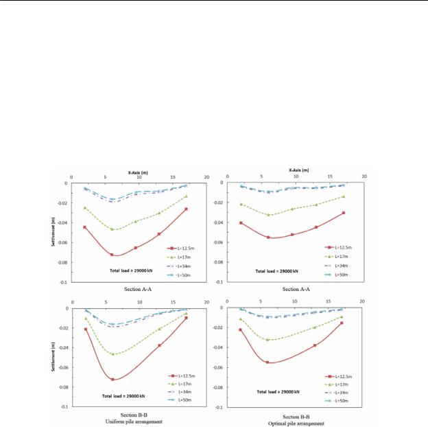
Раздел 4. Лабораторные и полевые исследования грунтов и фундаментных конструкций…
trends show that the settlement of the piled raft decreases with increasing pile length, and use of the optimal pile arrangement scheme considerably reduces the settlements. However, in comparing among the four pile length cases, the settlements of the foundation are reduced significantly when the pile length is increased from 12.5 m to 34 m, but the settlements are not further reduced when the pile length is increased by 1.5 times from 34 m to 50 m. This indicates that increasing the pile length produces good foundation performance, but there is an upper limit to the pile length beyond which very little additional benefit is obtained.
Figure 6. Comparison of the settlements between different pile length cases (Nguyen et al. 2014)
Effects of the number of piles
Increasing the number of piles is another option that is used commonly in design to reduce the total and differential settlements. This section investigates the effects of increasing the number of piles on reducing the settlements of piled rafts subjected to different column loads. Figure 7 presents the pile placement schemes for the models.
Figure 8 presents a comparison of the settlements along the A-A and B-B sections between the uniform and concentrated pile arrangement schemes and the effects of the number of piles on the foundation’s settlement. The general trend is that increasing the number of piles will decrease the settlements of a piled raft. However, it can be seen that the efficiency of reducing settlement by increasing the number of piles is relatively low. Although the number of piles is increased by more than twice (from n = 16 to n = 36), the maximum settlement of the founda-
229
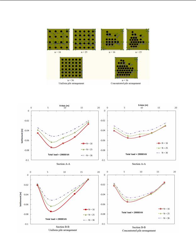
Современные геотехнологии в строительстве и их научно-техническое сопровождение
tion is reduced by only approximately 30% for the uniform pile arrangement and by approximately 10% for the concentrated pile arrangement.
Figure 7. Pile arrangement schemes for three cases of number of pile (Nguyen et al. 2014)
Figure 8. Comparison of the settlements between different number of pile cases (Nguyen et al. 2014)
Conclusions
This paper presents the experimental and numerical studies of large piled raft foundations on sand to investigate the method for optimal design. The study demonstrates the feasibility of the concentrated pile arrangement for reducing the total and differential settlements and the induced bending moment of piled raft founda-
230