

2011 rhb final revised 02-11-2011
.pdf
|
|
|
|
MODELS |
|
|
CHARACTERISTICS |
AN/PRC-117F(c) |
AN/PRC-152 |
AN/PRC-148 |
AN/PRC-119F |
AN/PRC-150C |
|
Encryption |
|
|
|
|
|
|
•Type: |
|
|
|
|
|
|
|
– ANDVT |
Yes |
Yes |
Yes |
|
Yes |
|
– Vinson |
Yes |
Yes |
Yes |
Yes |
Yes |
|
– KG–84 |
Yes |
Yes |
|
|
Yes |
|
– Fascinator |
Yes |
Yes |
Yes |
|
|
|
|
|
|
MODELS |
|
|
|
|
AN/PRC-117F(c) |
AN/PRC-152 |
AN/PRC-148 |
AN/PRC-119F |
AN/PRC-150C |
CHARACTERISTICS |
|
|
MBITR |
|
|
|
• Method: |
|
|
|
|
|
|
|
– SINCGARS |
Yes |
Yes |
Yes |
Yes |
|
|
– Havequick I |
Yes |
Yes |
Yes |
|
|
|
– Havequick I |
Yes |
Yes |
Yes |
|
|
|
– Serial Tone |
|
|
|
|
Yes |
|
– ECCM |
Yes |
Yes |
Yes |
|
|
|
– Freq Hop |
Yes |
Yes |
Yes |
Yes |
Yes |
• Fill Devices: |
|
|
|
|
|
|
|
– KYK-13 |
Yes |
Yes |
Yes |
Yes |
Yes |
|
– KOI-18 |
Yes |
Yes |
Yes |
Yes |
Yes |
|
– KYX-15 |
Yes |
Yes |
Yes |
Yes |
Yes |
|
– SKL |
Yes |
Yes |
Yes |
Yes |
Yes |
|
– AN/CYZ-10 |
Yes |
Yes |
Yes |
Yes |
Yes |
Immersion Depth |
1 meter |
20 meters |
2 to 20 meters |
1 meter |
0.9 meter |
|
SA Reporting |
Yes |
Yes |
Yes w/ RGU |
If equipped with |
No |
|
Capable |
|
|
|
optional internal |
|
|
|
|
|
|
|
GPS |
|
Special features |
Ship-to-Shore, |
Ship-to-Shore, |
Ship-to-Shore, |
NA |
Advanced |
|
|
|
Ground-to- |
Ground-to- |
Ground-to- |
|
Automatic Link |
|
|
Ground, and |
Ground, and |
Ground, and |
|
Establishment |
|
|
Air-to-Ground |
Air-to-Ground |
Air-to-Ground |
|
(ALE), |
|
|
Capable |
Capable |
Capable |
|
|
|
|
|
Submersible to |
Submersible |
|
|
|
|
|
20 meters. |
to 20 meters |
|
|
Terrain |
LOS: open to |
LOS: open to |
LOS: open to |
LOS: open to |
Ground wave: |
|
Restrictions |
slightly rolling |
slightly rolling |
slightly rolling |
slightly rolling |
wide open, |
|
|
|
terrain |
terrain |
terrain |
terrain |
flat terrain |
|
|
TACSAT: |
TACSAT: |
TACSAT: |
|
Sky wave: |
|
|
any terrain |
any terrain |
any terrain |
|
long-range |
|
|
|
|
|
|
communication |
1 |
When coupled with |
Windows Messaging |
Terminal software-equipped laptop. |
|
|
|
2 |
Commercial GPS capable (used with SA reporting feature). |
|
|
|
||
3 |
DAGR Is compatible, PLGR requires optional RGU (Remote Control Unit with GPS User Notification). |
|
||||
4 - 3

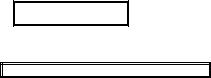
Table 4-1. FREQUENCY RANGES
|
High |
Very High |
|
Ultra High |
|
|
|
|
|
|
|||
|
Frequency |
Frequency |
Very High |
Frequency |
|
|
|
(HF) |
(VHF) Low |
Frequency |
(UHF) |
TACSAT |
UHF SATCOM |
1.6 to 29.999 |
30.000 to 89.999 |
90.000 to |
225.000 to |
243.000 to |
292.000 to |
|
|
MHz |
MHz |
224.999 MHz |
512.000 MHz |
270.000 MHz |
318.00 MHz |
|
long range |
LOS 2 |
LOS 2 |
LOS 2 |
Satellite |
Satellite |
|
LOS 1 |
|||||
1 |
Long-range LOS; capable of round-the–world communication due to longer physical wavelengths, which cause HF |
|||||
|
transmissions to “bounce” off terrain and be reflected by the Earth’s ionosphere instead of absorbed like VHF and UHF |
|||||
|
transmissions. This keeps the transmission bouncing, essentially trapped, between the ground and the Earth’s |
|||||
|
atmosphere. For this volatile capability to offer effective communications, several factors must be ideal. |
|
||||
2 |
Line of sight (LOS) frequencies; meaning that the range of radios is limited to direct line of sight for maximum |
|||||
|
effectiveness. Curvature of the earth, mountainous terrain, and dense vegetation will degrade LOS radio maximum |
|||||
|
range capabilities. |
|
|
|
|
|
3 |
Modern military communications rely on UHF Satellite Communication (SATCOM) or Dedicated Tactical Satellite |
|||||
|
Communication (TACSAT) for round-the–world real time secure voice and data communication. |
|
||||
4-2. MAN-PACK RADIO ASSEMBLY (AN/PRC 119F). To assemble a man-pack radio, you must first check and install a battery.
a.Inspect the battery box for dirt or damage.
b.Stand radio on its side with the battery cover facing up.
c.Check battery life condition (you will be using the rechargeable BB 390 batteries).
d.Place battery in box.
e.Close and latch the battery cover.
f.Return radio to upright position.
g.If you installed a used battery, then enter the battery life condition into the radio:
(1) |
Set FCTN to LD. |
||
(2) |
Press |
BAT, |
then CLR. |
(3) |
Enter |
number recorded on side of battery. |
|
(4) |
Press |
STO. |
|
(5) |
Set FCTN to |
SQ ON. |
|
h.Inspect and position the antenna.
(1)Inspect whip antenna connector on antenna and on radio for damage.
(2)Screw whip antenna into base.
(3)Hand tighten.
(4)Carefully mate antenna base with RT ANT connector.
(5)Hand tighten.
(6)Position antenna as needed by bending goose neck.
NOTE: Keep the antenna straight, if possible. If the antenna is bent to a horizontal position, you might have to turn the radio before you can receive and transmit messages.
i.Set up the handset.
(1)Inspect the handset for damage.
(2)Push handset on AUD/ DATA and twist clockwise to lock in place.
j.Pack.
(1)Place RT in field pack with antenna on the left shoulder.
(2)Fold top flap of field over RT and secure flap to field pack using straps and buckles.
k.Set Presets. Set--
(1)CHAN: 1
(2)MODE: SC
(3)RF PWR: HI
(4)VOL: Mid Range
(5)DIM: Full clockwise
(6)FCTN: LD
(7)DATA RATE: OFF
l.Single-Channel Loading Frequencies.
(1)Obtain Ranger SOI:
(2)Set FCTN: LD
(3)Set mode: SC
(4)Set CHAN: MAN, Cue, or set channel (1 to 6) where you want to store frequency
(5)Press FREQ: (Display will show "00000” or frequency RT is currently turned on)
(6)Press CLR: (Display will show five lines)
(7)Enter: The number of the new frequency. If you make a mistake with a number press CLR
(8)Press STO: (Display will blink)
(9)Set FCTN: SQ ON
m.Clearing of frequencies.
(1)Set Mode: SC
(2)Set CHAN: MAN, Cue or desired channel where frequency is to be cleared
(3)Press FREQ:
(4)Press CLR:
(5)Press Load, STO
(6)Set FCTN: SQ ON
n.Scanning of multiple frequencies.
(1)Load: All desired frequencies using "Single Channel Loading Frequencies" instructions
(2)Set CHAN: CUE
(3)Set SC: FH
(4)Set FCTN: SQ ON
(5)Press STO: (Display will say SCAN)
(6)Press 8: You can now scan more than one frequency
4-3. AUTOMATED NET CONTROL DEVICE. The RTO retrieves all necessary COMSEC and information from the ANCD. To retrieve the SOI from an ANCD:
a.Press the On button on the ANCD keypad.
b.Press the Letter Lock button to unlock the keys on the ANCD.
c.Press Main Menu key (onscreen)
Appl Date Time Setup
Util Bit
d.Using the arrow keys, scroll over to Appl and press the Enter button on the keypad.
e.Once you have entered into the Appl (applications) menu using the arrow keys, scroll over to SOI and press the
Enter button on the keypad. For example–
RDS SOI Radio.
4 - 5
(appl) < (Indicates that you are in the applications menu).
SOI menu will look like this:
Qref Group Net Sufx Pyro
Tmpd Set C/ S Find Memo
f.Using the arrow keys, scroll over to Set and press the enter button on the keypad.
g.In the Set menu, press Choose once.
Choose Send Receive
h.When the Choose menu opens, press the Enter key on the set, either 1 5 or 6 10.
i.After you choose the applicable set, the ANCD will return you to the SOI menu.
j.Using the keypad, scroll to Tmpd. Enter the number for the set you need that day. After you do this, the ANCD will
automatically return you to the SOI menu.
k. Using the arrow keys on the keypad, scroll over to Net and press Enter. The Net menu should look like this:
T05 < (time period) 1 < (platoon) / A < (company) / A3Q < (prefix).C 60.000.
NOTE: Get your frequency and the first part of your call sign from the Net menu.
l.After you get the information you need from Net, press the abort button on the keypad to return to the SOI menu.
m.Using the keypad, scroll to Sufx and press the Enter button.
n.Once you are in the Sufx menu, use the up and down arrow keys on the ANCD to locate your two digit designator. These two digits go at the end of your Prefix and together they are your call sign.
o.Once you finish, press the Off button on the ANCD to end operation.
4-4. BASIC TROUBLESHOOTING. You need basic troubleshooting skills in order to correct the simple communications problems that occur during a mission. Being able to quickly troubleshoot can make the difference in successful accomplishment of the mission and mission failure.
a.Check Radio Settings.
(1)Radio frequency: load proper frequency.
(2)Power output: set to HIGH power.
(3)Time if using frequency hop (FH): reset time.
(4)Crypto fill if using cipher text (CT): reload crypto from ANCD.
(5)Control knob: ensure radio is in ON position.
b.Check Radio Assembly/ Battery.
(1)Check antenna fitting: attach long whip or field expedient antenna
(2)Check hand mike fitting: ensure contacts are clean and fitting is properly secured to radio
(3)Check battery: install fresh battery
c.With line of sight (LOS) radios, you might have to move to higher ground to make radio contact, especially in densely vegetated or uneven terrain.
Section II. ANTENNAS
This section discusses repair techniques, construction and adjustment, field expedient antennas, antenna length and orientation, and improvement of marginal communications.
4-5. REPAIRS. Antennas are sometimes broken or damaged, causing communications degradation or failure. If you have a spare antenna, replace the bad one. When you have no spare, you [Ranger squad/ platoon] might have to construct an emergency
antenna. The following paragraphs suggest some ways to repair antennas and antenna supports, and to construct and adjust emergency antennas.
DANGER
RADIO TRANSMITTER
SERIOUS INJURY OR DEATH CAN RESULT FROM CONTACT WITH
THE RADIATING ANTENNA OF A MEDIUM-POWER OR HIGH-POWER
TRANSMITTER.
TURN OFF THE TRANSMITTER WHILE ADJUSTING THE ANTENNA.
a.Whip Antennas. When a whip antenna breaks in two, connect the broken part to the part attached to the base by joining the sections. To restore the antenna to its original length, add a piece of wire that is nearly the same length as the missing part of the whip. Lash the pole support securely to both sections of the antenna. Before connecting the two antenna sections to the pole support, clean them well to ensure good contact. If possible, solder the connections.
b.Wire Antennas. Emergency repair of a wire antenna may involve the repair or replacement of the wire used as the antenna or transmission line; or the repair or replacement of the assembly used to support the antenna.
(1)When one or more wires of an antenna are broken, you can repair the antenna by
reconnecting the broken wires. To do this, lower the antenna to the ground, clean the ends of the wires, and twist the wires together. Whenever possible, solder the connection.
(2) If the antenna receives damage beyond repair, construct a new one. Make sure that the length of the substitute antenna wires are the same length as those of the original.
(3) Antenna supports may also require repair or replacement. You can use anything as a substitute for the damaged support provided it is strong enough and insulated. If the radiating element were not properly insulated, then field antennas could short to ground, and will no longer work. Many common items make good field expedient insulators.
(4) The best are plastic or glass, for example, plastic spoons, buttons, bottle necks, and plastic bags. Though wood and rope are less effective insulators than plastic or glass, they are better than nothing. The radiating element (the antenna wire) should touch only this supporting (nonconductive) insulator and the antenna terminal. It should remain physically separated from everything else.
4-6. CONSTRUCTION AND ADJUSTMENT. Ranger squad/ platoons may use the following methods to construct and adjust antennas:
a. Construction. The best wire for antennas is copper or aluminum. However, in an emergency, use any wire you can
find.
(1) The exact length of most antennas is critical. Make sure that the emergency antenna is the same length as the original antenna.
(2) Antennas can usually survive heavy wind storms if supported by a tree trunk or strong branch. To keep the antenna tight and keep it from breaking or stretching when the trees sway, attach a spring or old inner tube to one end of the antenna. Another technique is to pass a rope through a pulley or eyehook. Attach the rope to the end of the antenna, and heavily weight the rope to keep the antenna tight.
(3) To ensure the rope or wire guidelines do not interfere with the operation of the antenna, cut the wire into several short lengths and connect the pieces with insulators.
b. Adjustment. An improvised antenna may change the performance of a radio set. The following methods can be used to determine if the antenna is operating properly:
(1) A distant station may be used to test the antenna. If the signal received from this station is strong, the antenna is operating satisfactorily. If the signal is weak, adjust the height and length of the antenna and the transmission line to receive the strongest signal at a given setting on the volume control of the receiver. This is the best method of tuning an antenna when transmission is dangerous or forbidden.
4 - 7
(2) In some radio sets, use the transmitter to adjust the antenna. First, set the controls of the transmitter to normal; then, tune the system by adjusting the antenna height, the antenna length, and the transmission line length to obtain the best transmission output.
4-7. FIELD EXPEDIENT (FE) OMNI DIRECTIONAL ANTENNAS. Vertical antennas are omni directional. The omni directional antenna transmits and receives equally well in all directions. Most tactical antennas are vertical; for example, the man pack portable radio uses a vertical whip and so do the vehicular radios in tactical vehicles. A vertical antenna can be made by using a metal pipe or rod of the correct length, held erect by means of guidelines. The lower end of the antenna should be insulated from the ground by placing it on a large block of wood or other insulating material. A vertical antenna may also be a wire supported by a tree or a wooden pole. For short vertical antennas, a pole may be used without guidelines (if properly supported at the base). If the length of the vertical mast is not long enough to support the wire upright, it may be necessary to modify the connection at the top of the antenna.
a. End Fed, Quarter, Half, or Full Wave Antenna. An emergency, end fed half wave antenna (Figure 4-1) can be constructed from available materials such as field wire, rope, and wooden insulators. Compute the length of the (one quarter, one half, or full wave) antenna by using the formula provided previously. Cut the wires as close as possible to the correct length (better the wire is too long than too short). The electrical length of this antenna is measured from the antenna terminal on the radio set to the far end of the antenna. The best performance can be obtained by constructing the antenna longer than necessary and then shortening it, as required, until the best results are obtained. Connect the antenna to the radio using either method (Figure 4-2A and Figure 4-2B).
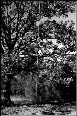
Figure 4-1. FIELD EXPEDIENT, END-FED QUARTER, HALF, OR FULL WAVE ANTENNA
4 - 9
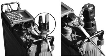
Figure 4-2A. COBRA HEAD |
Figure 4-2B. ANTENNA BASE |
|
|
b. Expedient 292-Type Antenna. Developed for jungle, these antennas, properly used, can improve communications. Their weight and bulk render them impractical for most squad or platoon operations, but the unit can carry the masthead and antenna sections only, and mount them on wood poles or from trees; or they can construct an expedient version ( Figure 4-3, Figure 4-4, and Figure 4-5) using any insulated wire and other available material. For example, most any plastic, glass, or rubber items or, if these are unavailable, dry wood, can serve as insulators:
(1) Use the planning considerations discussed in the next paragraph to determine the length of the elements (one radiating wire and three ground plane wires) for the desired frequency. Cut these elements ( A) from claymore or similar wire. The heavier the gauge, the better, but insulated copper core wire works best. Cut spacing sticks ( B) the same length as the ground plane wires. Place the sticks in a triangle and tie their ends together with wire, tape, or rope. Attach an insulator ( C) to each corner and one end of each ground-plane wire to each insulator. Bring the loose ends of the groundplane wires together, attach them to an insulator (C), and tie securely. Strip about 3 inches of insulation from each wire and twist them together .
(2) Tie one end of the radiating element wire to the other side of insulator and the other end to another insulator ( B). Strip about 3 inches of insulation from the radiating element ( C).
(3) Cut enough wire to reach from the proposed location of the antenna to the radio set. Keep this line as short as possible, because excess length reduces the efficiency of the system. Tie a knot at each end to identify it as the "hot" lead. Remove insulation from the "hot" wire and tie it to the radiating element wire at insulator ( C). Remove insulation from the other wire and attach it to the bare ground plane element wires at insulator ( C). Tape all connections and do not allow the radiating element wire to touch the ground plane wires.
(4) Attach a rope to the insulator on the free end of the radiating element and toss the rope over the branches of a tree. Pull the antenna as high as possible, keeping the lead in routed down through the triangle. Secure the rope to hold the antenna in place.
(5) At the radio set, remove about 1 inch of insulation from each end of the wire. Connect the ends to the positive side of the cobra head connector. Be sure the connections are tight or secure.
(6) Set up correct frequency, turn on the set, and proceed with communications.

Figure 4-3. COMPLETED EXPEDIENT 292-TYPE ANTENNA
4 - 11

Figure 4-4. COMPLETED EXPEDIENT 292-TYPE ANTENNA
|
Table 4-2. QUICK-REFERENCE TABLE |
|
Figure 4-5. COMPLETED 292-TYPE ANTENNA |
|||
|
OPERATING |
ELEMENT LENGTH |
|
|
|
|
|
FREQUENCY |
(RADIATING ELEMENTS AND |
|
|
|
|
|
IN MHz |
GROUND-PLANE ELEMENTS) |
|
|
|
|
|
30 |
2.38 m |
(7 ft 10 in) |
|
|
|
|
32 |
2.23 m |
(7 ft 4 in) |
|
|
|
|
34 |
2.1 m (6 ft 11 in) |
|
|
|
|
|
36 |
1.98 m |
(6 ft 6 in) |
|
|
|
|
38 |
1.87 m |
(6 ft 2 in) |
|
|
|
|
40 |
1.78 m |
(5 ft 10 in) |
|
|
|
|
43 |
1.66 m |
(5 ft 5 in) |
|
|
|
|
46 |
1.55 m |
(5 ft 1 in) |
|
|
|
|
49 |
1.46 m |
(4 ft 9 in) |
|
|
|
|
52 |
1.37 m |
(4 ft 6 in) |
|
|
|
|
55 |
1.3 m (4 ft 3 in) |
|
|
|
|
|
58 |
1.23 m |
(4 ft 0 in) |
|
|
|
|
61 |
1.17 m |
(3 ft 10 in) |
|
|
|
|
64 |
1.12 m |
(3 ft 8 in) |
|
|
|
|
68 |
1.05 m |
(3 ft 5 in) |
|
|
|
|
72 |
0.99 m |
(3 ft 3 in) |
|
|
|
|
76 |
0.94 m |
(3 ft 1 in) |
|
|
|
|
|
|
|
|
|
|
|
|
|
|
|
|
|
4 8. ANTENNA LENGTH PLANNING CONSIDERATIONS. The length of an antenna must be considered in the construction of field expedients. At a minimum a quarter of the frequency wavelength should be used as the length of the FE Antenna. Another important factor in LOS communications is the height of the antenna with relation to the receiving station. The higher the antenna the greater the range the radio transmission will have. Terrain and curvature of the Earth affect LOS communication by absorbing