

Ideal Op Amps
Op amps, (short for operational amplifiers) is an active circuit component. We will not discuss the internals of op amps in this wikibook, but will instead only consider the ideal case. Op amps have 2 input terminals and 1 output terminal.
Ideal op amps are governed by some very simple rules that allow an engineer to solve a circuit without having to know exactly how an op amp does what it does. These rules are enumerated as follows.
Op Amp has infinite impedance
Op Amp has infinite bandwidth
Op Amp has infinite voltage gain
Op Amp has Zero output impedance
Op Amp has Zero offset (error)
We will consider an op amp with 2 inputs (x and y), and an output (z).
There is 0 voltage difference between the terminals x and y.
There is 0 current flowing on terminals x and y.
There is 0 current flowing on terminal z.
Independent Sources
Independent sources produce current/voltage at a particular rate that is dependent only on time. These sources may output a constant current/voltage, or they may output current/voltage that varies with time.
Dependent Sources
Dependent sources are current or voltage sources whose output value is based on time or another value from the circuit. A dependent source may be based on the voltage over a resistor for example, or even the current flowing through a given wire. The following sources are possible:
Current-controlled current source
Current-controlled voltage source
Voltage-controlled current source
Voltage-controlled voltage source
Dependent sources are useful for modelling transistors or vacuum tubes.
Turning Sources "Off"
Occasionally (specifically in Superposition) it is necessary to turn a source "off". To do this, we follow some general rules:
Dependent sources cannot be turned off.
Current Sources become an Open Circuit when turned off.
Voltage Sources become a Closed Circuit when turned off.
Occasionally it is written that the source is "removed" from the circuit, because often it is physically possible to remove the source component (be it a battery, or a plug, or any other source component) physically from the circuit. We can't inactivate these sources.
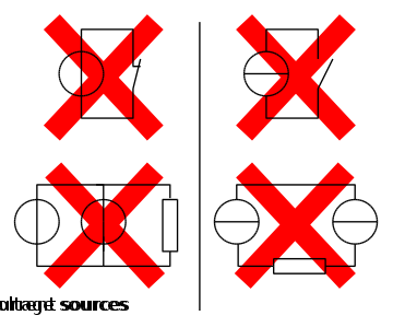
Source Warnings
The following image shows some configurations of current and voltage sources that are not permissable, and will cause a problem in your circuit:
Switches
A switch
then is a circuit element that is an open-circuit for all time t
< T0,
and acts like a closed-circuit for all time
![]() .
.
Unit Step Function
Before talking about switches, we will introduce the Heaviside step function u(t) (also known as the unit step function). The step function is defined piecewise as such:
[Unit Step Function]
![]()
This function provides a mathematical model for electrical engineers to describe circuit elements that change between boolean states (on/off, high/low, etc).
Transducers
A transducer is a circuit component that transforms electrical energy into another type of energy. Some examples of transducers are actuators and motors.