

2.2.3.2. Secondary indicating systems
Oil/fuel temperature
There is a need for accurate measurement of fluid temperatures on and around the engine, e.g. fuel, engine lubrication (lube) oil and hydraulic oil. The typical temperature range of these fluids is between —40 and +150°C. When lube oil operates at high temperatures, its viscosity reduces and its lubrication performance decreases. This leads to engine wear and eventual failure of bearings or other engine components. When lube oil operates at low temperatures, its viscosity increases, which has an effect on starting. When fuel is exposed to high temperatures, it can vaporize, causing fuel delivery problems and a potential risk of explosion; at low temperatures, ice formation can occur leading to blocked filters.
The flight compartment indicator is a moving coil meter connected in series with the resistance winding of a resistance temperature device (RTD). As the temperature changes, the resistance changes and this causes the pointer to respond accordingly. The meter is acting as an ammeter, but since there is a linear relationship between temperature and resistance, and since we know (from Ohm's law) that the current in a circuit will vary in accordance with resistance, the moving coil meter can be calibrated as a temperature indicator.
This is all very well provided that the power supply voltage does not change. To illustrate this problem, assume a given temperature and hence a specific resistance of the RTD. The effect of a varying power supply voltage will be to vary the current through the RTD and meter; this would change the reading even though temperature has not changed; an undesirable situation. The method employed to overcome this is a circuit called the Wheatstone bridge. This circuit has a number of applications and is ideally suited for the RTD.
Vibration
Unbalanced shafts on a gas turbine engine can cause damage, particularly at high rotational speeds. These conditions can be anticipated by measuring the engine's vibration. Sensors used to detect vibration are based on piezoelectric crystals; a small electrical charge is created when the crystal is vibrated. Each engine has a sensor(s) located at strategic locations; the output is fed into a processor and displayed on an indicator, see Fig. 15.
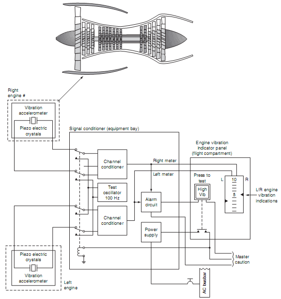
Figure 15 Vibration sensor system
The output from the processor can also be used to illuminate a warning light when pre-determined limits are exceeded. A test switch (incorporated into the light) is used to energize a relay (or equivalent electronic switch); this inserts a known frequency into the processing circuit to generate a warning. The vibration warning circuit also activates the master caution system.
Fluid pressure
Typical fluid pressures being measured on the engine include lubrication oil and fuel. There are two basic methods used to measure fluid pressure: the Bourdon tube or a capsule. The Bourdon tube comprises a tube formed into a curved or spiral shape. As the applied pressure from the fluid system increases, the tube will tend to straighten out, while a reduced pressure will cause the tube to return to its original shape. This movement is transferred via the gear mechanism to move a pointer. The pointer moves across a scale, thereby providing a direct reading of pressure. The other method used for measuring fluid pressure is with a capsule. As pressure is applied by the fluid, the capsule expands. This moves an iron bobbin within the envelope of two inductor coils. (The principles of Bourdon tubes, pressure capsules and measurement systems are described in lecture 2.5)