

Lecture 2.6
2.2.3. Airplane engine indicating systems electrical equipment
Engine indications can be broadly divided into primary and secondary systems. Some indication systems are unique to gas turbine, turboprop or piston engines, some are common to all types. Primary indicators include:
• speed
• temperature
• thrust
• fuel flow.
Secondary indicators include (but are not limited to):
• oil temperature
• oil quantity
• oil pressure
• vibration.
Measurements are made by a variety of transducers; these are devices used to convert the desired parameter, e.g. pressure, temperature, displacement etc. into electrical energy. The locations of engine instruments is normally between the two pilot's panels, see Fig. 1.
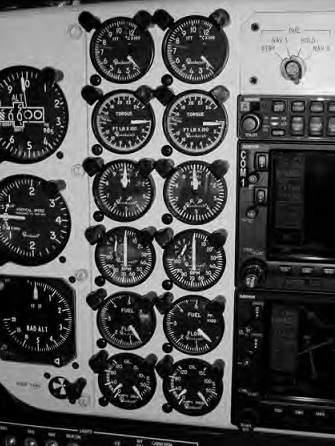
Figure 1 Typical engine instruments
2.2.3.1. Primary indicating systems
Engine speed
This is a primary engine indication used on both piston and gas turbine engines. It is one of two methods used to indicate thrust on gas turbine engines (the other being EPR). In gas turbine engines, the usual practice is to display a percentage of maximum revolutions per minute (r.p.m.) rather than actual r.p.m. Typical gas turbine engine speeds are in the order of 8000-12,000 r.p.m. The mathematical notation for rotational speed is N. gas turbine engines can have up to three shafts (or spools), these are referred to as low, intermediate and high-pressure shafts (LP, IP and HP). Alternatively, they are referred to numerically; the individual shaft speeds are therefore Nl5 N2 and N3. Engine speed is monitored by the crew at all times; particularly during start and take-off to make sure that engine limits are not exceeded. The two principal types of engine speed transducer are the tachometer and variable reluctance device.
Tachometer system
The tachometer indicating system is a small three-phase AC generator connected via a mechanical link to engine accessory gearbox. A tachometer system is found on most general aviation aircraft. Referring to fundamental principles, the tachometer's output increases with increased engine speed; the output is rectified and connected to a moving coil meter. The output from the generator is supplied to a three-phase AC synchronous motor in the indicator; see Fig.2.
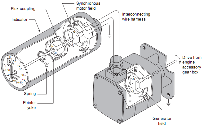
Figure 2 Tachometer system schematic
The AC generator tachometer consists of a permanent magnet that is rotated inside stator windings wound in a three-phase star configuration. Three stator outputs are connected to the stator windings of the motor. As the engine turns, the permanent magnet induces currents in the stator windings. The three-phase output induces a rotating field in the motor stator windings.
Referring to Fig. 3, a permanent magnet is attached to the rotor shaft of the synchronous motor; this is connected to the pointer of the indicator. As the stator field rotates, the permanent magnet keeps itself aligned with the field. A second permanent magnet is attached to the indicator rotor; this is located within a drag cup, see Fig. 4. As this second magnet rotates, it induces eddy currents in the drag cup. These currents produce their own magnetic fields in opposition to the rotating magnet.
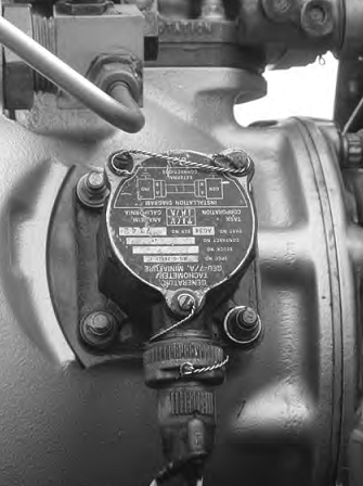
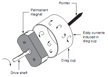
Figure 3 Tachometer system installation Figure 4 Drag cup features
When the rotating magnet increases in speed, the drag (or torque) on the drag cup increases. A hairspring attached to the shaft opposes this torque; the net result is the pointer moves across the scale in proportion to the speed of the engine shaft.