

Module 2
UNIT 3. PARALELLING ALTERNATORS
3.1. Autosynchronizing acGs
AUTO SYNCHRONIZING OF ACGs
General. When it is intended that two or more generators be operated in parallel, means are to be provided to divide the reactive power equally between the generators in proportion to the generator capacity.
3.13.3(b) Reactive load sharing. The reactive loads of the individual generating sets are not to differ from their proportionate share of the combined reactive load by more than 10% of the rated reactive output of the largest generator, or 25% of the smallest generator, whichever is the less.
3.13.3(c) kW load sharing. In the range between 20% and 100% of the sum of the rated loads of all generators, the kW load on any generator is not to differ more than ±15% of the rated output kW of the largest generator, or 25% of the rated output kW of the individual generator, whichever is the less, from its proportionate share. The starting point for the determination of the foregoing load-distribution requirements is to be at 75% load with each generator carrying its proportionate share.
Unquote
The Basics
Main generator units (steam turbine, diesel driven and shaft driven) have to be run in parallel to share a total load that exceeds the capacity of a single machine. Changeover of main and standby generator units require a brief parallel running period to achieve a smooth transition without a blackout situation.
For the sake of simplicity and security, it is normally not possible or advisable to run a main generator in parallel with either the emergency generator or the shore supply. Circuit breaker interlocks are incorporated to prevent it. Parallel running is achieved in two stages -synchronising and load sharing. Both can be carried out automatically but manual control is still in common use and is generally provided anyway as a back-up to the auto control mode.
The generator already 'on the bars' is called the running machine and the generator to be brought into service is the incoming machine.
In order to parallel the incomer smoothly, it must be synchronised with the running generator (or the bus bars); the following conditions are essential:
Same voltage
Same frequency
Same phase sequence
In practice, one may find it difficult to adjust the speed of the incoming machine so that the pointer of the synchroscope is stationary at 12 o'clock. Such a condition is not essential and a more practical proposition is to have the pointer rotating slowly in the 'Fast' direction and to close the paralleling switch at about 11 o'clock. Due to the time lag of the operating mechanism and human response, actual synchronising will thus take place closer to the 12 O'clock position, and the machine, running fast will be slowed down slightly while taking a small proportion of the load.
If the incoming machine is synchronised when it is running slow, it would slow down further and draw a motoring current, which may operate its reverse-power relay and 'trip' the circuit-breaker of the machine already on the 'bars' due to overloading.
The likely consequences of attempting to close the incomer's breaker when the generators are not in synchronism are that at the instant of closing the breaker, the voltage phase difference causes a large circulating current between the machines; this results in a large magnetic force to 'pull' the generators into synchronism. This means rapid acceleration of one rotor and deceleration of the other. The large forces may physically damage the generators and their prime movers, which may include deformation of the stator windings, movement between the stator core and frame, failure of the rotor diodes in brushless machines, twisted rotor shafts, localised crushing of shaft-end keyways and broken couplings. Tie large circulating current may also trip each generator breaker. Severe vibration of is also at symptom of loss of synchronism. This will be accompanied by flashover at the slip rings in the case of alternators that have a rotating armature. The ultimate result is a blackout, danger toe embarrassment!
Check-Synchronising Unit
This unit uses an electronic circuit to monitor the voltage, phase angle and speed (frequency) of the incoming generator with respect to the bus bars i.e., it prevents faulty manual synchronising. 'Check Synchronising' modules are often provided with a manual over-ride switch for use in an emergency. This can lead to problems if the over-ride is left activated after the emergency.
Auto-Synchronising
This does everything an operator would do. It senses and controls the voltage and frequency then initiates a circuit-breaker 'close' signal (of the incoming alternator) at the correct instant. The auto-synchronising equipment uses electronic circuits to monitor the magnitude of voltage, frequency and phase angle difference, and then acts to regulate them until they are equal to the existing parameters of the bus bar. (Refer Figure 10.2). Usually, one set of either check or auto synchronising units is switched between a set of generators as and when required. When an incoming generator has been successfully synchronised, the synchronising equipment should be switched off. The total bus bar load can now be shared between generators or totally transferred to the new machine. In a parallel operation, the governor of the alternator's prime mover directly controls power (kW) while its AVR trimmer or hand voltage regulator controls reactive volt amps (kVAr) or power factor. Figure 10.3(a) is similar to Figure 10.1(b) except for the fact that while synchronising is automatic, the process has to be manually initiated. However Figure 10.3(b) depicts a completely automatic system's flow chart.
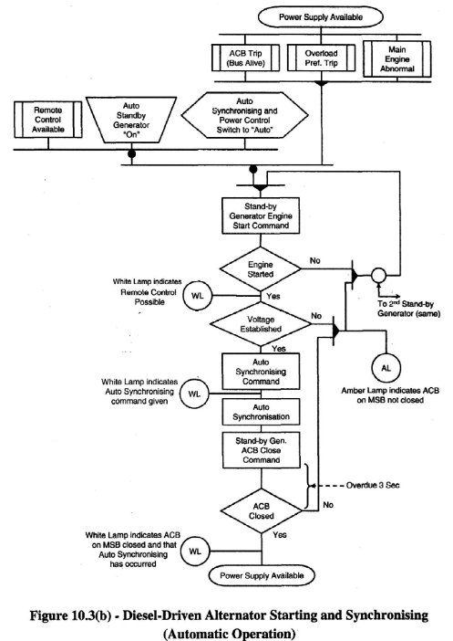
alternator starting and synchronizing (automatic operation)
Synchronising with the aid of Lamps
As a back-up or alternative to the synchroscope, a set of lamps may be used. The lamp method of synchronising makes use of filament lamps, so connected across the contacts of the paralleling switch that the intensity of the illumination varies continuously i.e., in each case the lamps are connected between the incoming generator and the bus bars. The correct synchronised state may be indicated by the 'Sequence' method that utilises 3 lamps.
The 'Sequence' method displays a rotation of lamp brightness, which indicates whether the incoming machine is running fast (clockwise) or slow (anticlockwise). As with the synchroscope in Figure 9.41, the lamps' sequence must appear to rotate slowly clockwise. Correct synchronisation occurs when the top or 'key' lamp is dark and the two bottom lamps are equally bright. The error in the frequency of the incoming machine as compared with bus bar frequency is shown by the rate at which the lamps 'darken' or 'brighten'. Figure 10.4 depicts the usual 'Sequence' or 3-lamp method. For three-phase systems, although the direct connection of three lamps across the contacts of each line or cross-connecting of the lamps are methods which can be used, the Siemens-Halske arrangement as shown in Figure 10.4 and explained in Figure 10.5, is favoured.
 arrangement
of synchronizing lamps
arrangement
of synchronizing lamps
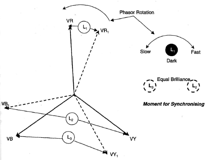
Phasor Rotation while Synchronising
This method not only indicates the correct instant for synchronising but also indicates when the incoming alternator is running fast or slow relative to the bus bar voltage. From the superimposed phasor diagrams of Figure 10.5 it will be seen that when running 'Slow', the lamps will glow in the order Li, L3, L2 and so on. If the incoming machine is running 'Fast' the lamps will glow in the order Li, L2, L3 and so on.
When the machines are in phase, then vectors 'VR' and 'VRi' will be aligned and therefore 'L,' will be dark, 'VY' and 'VBi' will be 120° apart and therefore '1^' will be approaching maximum luminosity, and the same will be for 'L3' with 'VY!' and 'VB' 120°.
So, if the lamps were arranged in a triangular pattern they would tend to brighten in a clockwise direction when the incoming generator is running faster than that which is already running; in short the frequency will be slightly higher. The moment for synchronising is with the 'key' lamp Li 'dark' and the other lamps L2 and L3 glow equally but not at full brilliance. Alternatively (or in addition) synchronising instruments may be used as shown in Figure 10.6. After successful synchronisation, the generator load should be shared equally, provided the alternators are similarly rated.
 Synchronising
Instruments
Synchronising
Instruments
Synchronising with the Aid of a Voltmeter
To monitor the correct instant for synchronising without the aid of a synchroscope or synchronising lamps, connect a pair of 500V voltmeter probes across one phase of the incoming machine circuit breaker. Adjust the generator speed until the voltmeter slowly fluctuates from zero to maximum. Close the breaker when the voltmeter passes through zero.
Parallel Operation
In order to parallel generators, the prime movers must be in proper working order. For example, the diesel engines need to be mechanically sound and properly tuned. The governors must be set properly. Before you ever consider major adjustments on the distribution switchboard, you must consult the operation and maintenance manual of the prime mover.
If the prime movers do not operate with the expected speed characteristics, then there is no possible way for you to compensate for their inaccuracies at the switchboard. For a paralleled alternator to take its share of the load, it is necessary to study the effects of two possible adjustments possible - namely:
Operation of the field regulator i.e. excitation control
Operation of throttle or steam valve i.e. speed control.
With two alternators in parallel, an increase in excitation of one machine raises the generated EMF and should tend to make it bear a greater share of the load. However, the machine cannot slow down since it is "tied" synchronously to the system and thus the governor of the prime-mover is unaffected. No action results in causing the machine to bear greater loads. As will be seen, the operation of the excitation control system merely causes a wattles current, which circulates in the paralleled machines and the bus bar system. This current lags the generated EMF by an angle <p and the load can be equated to EI Cosф. The kW load thus remains constant to maintain an unvaried governor setting. To change the distribution of load between alternators in parallel, the throttle valves must be manipulated.
We thus see that for two alternators in parallel, since the speeds (frequencies) must be identical, the kW loading on each machine must be related to the prime-mover input power i.e. to the amount of operation of the throttle valve and cannot be controlled by the excitation. The effect of excitation and throttle control will now be considered in detail. The parallel operation of alternators may be studied under two distinct considerations:
The first would be parallel working with an 'infinite bus bar', as constituted by shore-based power stations linked through a national transmission grid system. An ideal case of infinite bus bars is one where the system is so large, in comparison with a single alternator, that its voltage and frequency are unaffected by the behaviour of the alternator.
The second consideration is of importance to the marine engineer, since it relates to working on board a ship. Here, bus bar voltage and frequency can be altered by local conditions and the more common case, of two or more alternators running in parallel, is therefore stressed upon in this chapter.